Environmental Test App – Selecting an Environmental Test Chamber
To get the best value, here's what you need to know before you buy your next test chamber.
Your company has just developed a new product, and now it is your job to select an environmental chamber to test it. The product must be tested at various conditions to ensure its quality and reliability. Where do you start? What will determine your selection criteria? Price, quality, capabilities .
As with any major purchase, several items must be considered before making the final decision. Many people are tempted to buy on price only. However, as we know, you get what you pay for.
Quality, reliability, and service after the sale all add up to the value of your purchase. Value often is mistaken for low price. Over the life of the unit, that can become a costly mistake.
Many different types of test chambers are available. Your application is primarily going to determine the type of chamber you need. The better you relay that information to your supplier, the better your chamber will match your needs. How big must the chamber be? What is being tested? Is it going to be air cooled or water cooled? What temperature range is needed? These are just a few of the necessary questions that must be answered before purchasing a test chamber.
Chamber Types and Sizes
Reach-In Chambers
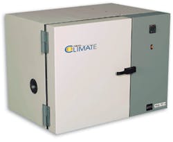
Reach-in chambers vary in size from 0.5 ft3 to more than 70 ft3 (Figure 1). Virtually any environment can be created in these chambers. Temperature, humidity, altitude, rain, solar and vibration are just a few.
Figure 1. Reach-In Chamber
Walk-In Chambers
Walk-in chambers can be just big enough to step into or large enough to drive vehicles into. There are two major types of walk-in chambers: modular and welded.
Modular walk-ins are constructed from pre-formed panels with urethane foam insulation, similar to walk-in refrigeration units you see at restaurants and supermarkets. The temperature and humidity range must be limited due to this construction. Normally, the maximum high temperature for modular walk-ins is between 100 C and 121 C. The humidity range typically is limited to 70 C and 95% RH.
Welded walk-ins are constructed like reach-in chambers. The internal chamber is welded together to withstand more extreme temperature and humidity ranges. This type of walk-in chamber also may withstand altitude conditions. Due to the additional labor to construct this type of chamber, it is much more expensive than a modular walk-in.
Thermal Shock Chambers
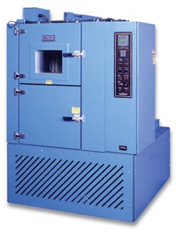
Thermal shock chambers come in many different sizes and configurations (Figure 2). These chambers can move the product from one temperature condition to another within a matter of seconds.
Figure 1. Thermal-Shock Chamber
Moving from a high temperature to a low temperature quickly thermally shocks and stresses the product. By performing these tests, the manufacturer can check the reliability of its process.
Temperature Range
The next major distinction is the temperature range in which the chamber will operate. Most manufacturers have a standard high temperature range of 177 C to 190 C for reach-in chambers and welded walk-ins. Temperatures up to 537 C can be achieved with special insulation and construction.
To cool the chamber, several options are available. The two major categories are expendable refrigerant and mechanically cooled.
Expendable refrigerants are liquids/gases that can be injected directly into the space being cooled. As the liquid enters the chamber, directly or through a fin coil, it absorbs heat and flashes to a gas. The gas then is vented out of the chamber.
The two most popular refrigerants are liquid nitrogen (LN2) and liquid carbon dioxide (CO2). Cryogenic temperatures down to -184 C can be achieved with LN2. On the other hand, CO2 can only achieve temperature down to -68 C. Both of these gases are environmentally safe and can be vented to the atmosphere.
It is imperative that the gases be vented outdoors. These gases displace oxygen, and asphyxia can occur if the chamber is not properly vented.
Mechanically cooled refrigeration systems are similar to the type used in home refrigerators. They use a compressor and circulate a refrigerant around a closed-loop system. The ultimate low temperature required by your testing determines the type of refrigeration system needed.
Single-stage refrigeration systems typically can pull the temperature in the chamber down to -34 C. Some manufacturers rate their single-stage systems down to -40 C. However, due to the refrigerant used, there is very little cooling capacity available at -40 C. For continuous operation at -40 C and below, most manufacturers recommend a cascade refrigeration system.
Cascade refrigeration systems have two separate systems working to cool the chamber down to a low of -85 C. The first-stage refrigeration system cools and condenses the refrigerant in the second stage. The second-stage refrigerant flows through an evaporator located in the chamber that cools the air. These systems can become very complex depending on the application.
A couple of years ago, a third refrigeration option became available. It is the patented, single-stage Tundra Refrigeration System from Cincinnati Sub-Zero Products that cools the chamber down to -45 C. It uses a common refrigerant and can operate continuously at -40 C.
Since most low-temperature environmental testing is done at -40 C, it is a good alternative to buying a cascade system. It uses less energy (up to 40% less) and is less complex than a cascade system. There also are fewer parts compared to the cascade system, which means fewer items to fail over time. At warmer temperatures, the system also can handle large live-load conditions.
Humidity Range
Humidity is probably one of the most misunderstood topics when it comes to environmental test chambers because the relative humidity (RH) percentage is temperature specific. For example, the amount of moisture in the air at 20 C and 50% RH is not the same as 10 C and 50% RH. As the temperature of air is decreased, its capability to hold moisture also is reduced.
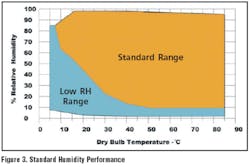
The standard temperature/humidity range for most chambers is 7 C to 85 C with 10% to 98% RH, limited by a 5 C dew point. The limitation of a 5 C dew point can be very confusing.
Since the amount of moisture varies at every temperature, the chamber manufacturers use dew point to describe the RH limitation. Inside the chamber, there is a refrigerated coil controlled at 5 C or slightly below. Moisture in the chamber will be attracted to the cold surface and condense. The accumulated water is drained out of the chamber, lowering the relative humidity. The refrigerated coil is never below freezing so frost will not develop.
The best way to understand this is to refer to Figure 3. If you follow the bottom line of the standard range section of the graph, those temperatures and humidities represent the 5 C dew point.
For example, the lowest humidity level achievable at 20 C is 40% RH. At 50 C, the chamber will achieve 10% RH. It must be operated within the limits set by the manufacturer. Damage to the refrigeration system can occur if points outside of the standard range are attempted.
To achieve lower humidity levels, most manufacturers offer a low RH package. It normally includes a dry-air purge system and refrigeration valves to allow the refrigerated coil to go below freezing.
The low RH range in Figure 3 is achievable when the dry-air purge and frozen coil are activated. There is a potential for the coil to accumulate frost at these conditions. However, the dry-air purge helps to offset this by maintaining a positive pressure in the chamber and sublimating some of the accumulating frost off the coil.
Temperature Change Rate
The requirements for temperature change rates continue to get faster and faster. It is not uncommon to see a 10 C, 15 C, or 20 C/min change rate specified. By incorporating faster change rates, total test time can be reduced. Products also can be thermally stressed at faster change rates to identify reliability problems. However, be careful assuming the part temperature is changing at the same rate as the air.
Every chamber manufacturer has different airflow volumes inside their chambers. The airflow must have enough volume to support the refrigeration system. The typical air velocity in most reach-in chambers is approximately 100 ft/min through the work space. This velocity works well for steady-state and temperature-cycling testing. However, the part temperature will lag behind the air temperature with this airflow.
Air velocity across the part should be much higher to keep it closer to the chamber air temperature during transitions. Typically, 500 ft/min or more is required to move the part temperature at a similar rate to the air temperature. It is a necessity in thermal shock applications to have airflow this high.
For most temperature and humidity applications, the airflow in reach-in chambers is adequate for the test. As the temperature is raised or lowered in the chamber, the air expands and contracts. Since the chamber is a sealed compartment with the exception of a small drain, the expansion and contraction of the air cause positive and negative pressure to be generated.
When the air temperature in the chamber is changed quickly (10 C, 20 C, 30 C/min), more than 0.25 psi differential can be created. This does not sound like a lot, but over a large surface like a chamber wall, the pounds of force can become large. For example, a 32 ft2 chamber has a side wall that is 38″ • 50″ (1,900 in.2)
1,900 in.2 • 0.25 lbf/in.2 = 475 lb
of force exerted on the wall
This force actually will be exerted on all the walls.
To offset this reaction, most manufacturers install some type of pressure-relief vent. The vents normally are closed to limit the infiltration of outside air during operation. When a fast transition is started, the vent either will draw in outside air for a pull-down or exhaust chamber air during a heat-up.
By allowing the chamber to breathe, the force on the walls is greatly reduced. It still is not uncommon to see the walls deflect in or out during a fast transition. Since this movement stresses the construction of the chamber, it is imperative that the chamber be well built.
Product in Chamber
This seems very basic: What is in the chamber and how much? If all the details are not given to the chamber manufacturer, the resulting selection may not be best for your application.
For example, you are testing hydraulic valves under pressure and various temperatures. Hydraulic lines enter and exit the chamber through an access port. Rarely, if ever, does a fluid leak occur in the chamber. This does not concern you since the warmest temperature achieved in the chamber is well below the auto-ignition point of the fluid.
But, if a leak happens, the chamber will be at risk of an explosion because the standard nichrome wire heater used in most chambers can exceed 1,000 F surface temperature. For this type of application, a temperature-limited sheath heater must be used.
There are many scenarios that could be used for examples, but the bottom line is to make sure you give your chamber manufacturer all the details of your tests.
Construction
Chamber construction is a critical area that needs to be evaluated when making a purchase. Most chambers have painted exteriors and stainless steel liners. It is easy to believe they are all built the same way. However, when you evaluate the details, you will see differences that can greatly affect the long-term reliability of the chamber.
Most of these differences relate to the way seams are connected for the stainless steel liner. Are the seams welded, pop-riveted, or screwed together? How are the ports fastened to the stainless steel liner and the outer cabinet?
When leaks occur in the stainless steel liner, a path is opened for moisture to travel in and out of the chamber, especially when the chamber is used for temperature and humidity testing. The humid air in the chamber finds the leak and condenses in the insulated area.
Most chamber manufacturers use fiberglass insulation similar to what is installed in the walls of your house. When moisture condenses on the insulation, it becomes saturated like a sponge and loses its insulating capability. The walls of the chamber then have less insulation, and that can affect the temperature and humidity performance. The water in the insulated space eventually will rust the outer sheet metal and allow water to leak onto the facility floor. A chamber with continuously welded seams is much less likely to develop leaks than a chamber assembled with other methods.
Another point of consideration should be the access ports. As the pressure in the chamber goes up and down during temperature transitions, the walls will deflect.
The ports connect the inside chamber to the external cabinet. As the inside walls move from the expansion and contraction of air, the port transfers that movement to the outer cabinet. For that reason, the connection between the port and the chamber must be extremely durable to withstand the frequent movement.
Chamber manufacturers use several methods to install ports, ranging from pop-riveted and caulked to fully welded. Again, a welded port will hold up better than other fastening methods.
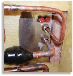
Another area that can be compromised over time is where the refrigeration lines penetrate the stainless steel chamber. The refrigeration lines generally are copper tubing. If any sharp edges touch the tubing, a refrigerant leak will develop. A good method to eliminate the possibility of abrasion is to install the tubing in sleeves where it penetrates the chamber. As movement occurs, the lines will not be exposed to sharp edges (Figure 4).
Air-Cooled or Water-Cooled Chamber
The refrigeration system removes heat from the product and the air that lowers the temperature in the chamber. The heat is moved through the refrigeration system and output at the condenser. There are primarily two choices when it comes to condensers: air cooled or water cooled. Each one has its positives and negatives.
Most small chambers come stand-ard as air cooled. The only utility connection required is power. This is very convenient for moving a chamber from one area to another.
Some items, however, need to be considered with air-cooled units. First is the overall heat that is introduced into the room where the chamber is located since most chambers are in air-conditioned areas.
For example, a chamber that has a 2-hp cascade system will output approximately 24,000 Btu/h into the room under full load. When the chamber is at set-point, it will introduce between 12,000 to 15,000 Btu/h into the room. The smaller the room where the chamber is located, the more critical it is that the air-conditioning system can handle the additional heat load.
A general rule of thumb for heat output is the following: Horsepower of refrigeration system multiplied by 12,000 Btu/h. If a chamber is going to be installed in an area that is not air-conditioned, tell the chamber manufacturer. The chamber may not work dependably if the ambient temperature regularly exceeds 29 C to 32 C.
Dirt is the second item to consider for an air-cooled system. Large volumes of air are passed through the condenser constantly. Most condensers are located near the floor, which allows them to pick up dirt easily. The condenser must be clean for the system to perform and work efficiently. This requires someone to clean the condenser at regular intervals.
If the chamber is located in a dirty environment, the condenser can become clogged very quickly. Restricted airflow will cause the refrigeration system to run at high pressure, tripping the high-pressure safety. If this environment is the destination for a test chamber, a remote air-cooled condenser or water-cooled should be considered. The air-cooled condenser is removed from the chamber and placed in another location, normally outdoors.
On the surface, this sounds like the best option since the heat and noise are moved outdoors. However, this type of system is more complicated and expensive to install for several reasons. Refrigeration piping must be sized and installed properly for the application, penetrations through the building roof or wall must be done by qualified personnel, a concrete pad or proper mounting on the roof for the remote air-cooled condenser must be installed, and the roof must be able to support the weight of the remote air-cooled condenser.
This type of installation normally requires bids from refrigeration, electrical, and roofing contractors. As you can see, installation can become very involved.
If your facility has process water pumped throughout the building and is routed to a cooling tower/dry cooler, a water-cooled chamber may be used. A water-cooled unit is easy to install and maintain.
Be sure to ask your chamber supplier for the water-flow and pressure requirements for the unit. The capacity of the process water system should be verified before purchasing the chamber. Most problems with water-cooled systems are due to inadequate water flow or differential water pressure supplied to the chamber.
Summary
It is critical that you provide all the information for your test requirements to your test-chamber supplier. This will ensure the best chamber for your application. Other items to keep in mind are the construction methods used by your supplier, the location of the chamber, and supplier service after the sale.
About the Author
Eric Berchtold is chief engineer at Cincinnati Sub-Zero Products where he has been employed for 16 years. He holds a B.S. in mechanical engineering technology from the University of Cincinnati. Cincinnati Sub-Zero Products, Industrial Division, 12011 Mosteller Rd., Cincinnati, OH 45241, 513-772-8810, e-mail: [email protected]
FOR MORE INFORMATION
on environmental test
chamber selection
www.rsleads.com/410ee-204

