Accelerometers are essential sensors used in a wide range of applications including shock and vibration testing, car safety systems, and today's hand-held consumer devices. Generally, they sense the motion of a mass moving in response to acceleration and convert it to an electrical signal.
Many electrical and mechanical properties have been used to accomplish this. For example, an accelerometer's so-called proof mass usually is coupled to the housing by a spring. The force exerted by a spring is given by F = kx where k is the spring constant and x is the amount the spring has been deflected from its rest position.
Newton's second law of motion relates force, acceleration, and mass as F = ma. Because the opposing forces are equal, a = kx/m, which means that acceleration of the proof mass m is directly proportional to the distance it moves relative to the housing.
Capacitance, resistance, and inductance all are suitable variables for the measurement of distance. In some accelerometers, the proof mass is supported on one or more cantilevered beams. As the beams deflect under acceleration, the spacing of capacitor plates attached to the ends of the beams changes, altering the capacitance. Typically, the relationship between capacitance and acceleration is not linear, but an accelerometer using this principle can be calibrated and linearized to provide repeatable, accurate readings.
Similarly, strain gages change their resistance in response to the bending of a supporting beam or diaphragm to which they are attached. A moving iron mass can be used as the core of a linear variable displacement transformer (LVDT) that measures the core's position.
If the proof mass is a permanent magnet, it can directly induce a voltage in a surrounding coil as it moves in response to acceleration. However, in this case, it's the velocity of the mass that is being sensed, not its displacement. Geophones, the sensors used in seismic testing, operate on this principle.
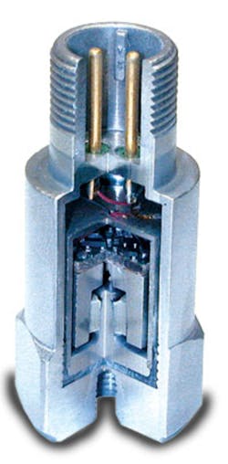
Figure 1. Cut-Away View of Piezoelectric Accelerometer Model AC102-1ACourtesy of CTC
Piezoelectric materials change their charge distribution when deformed. For example, as shown in Figure 1, a cylindrical proof mass is bonded to the outer circumference of a ring of piezoelectric crystal. The inner diameter of the ring is bonded to the base of the accelerometer. As the mass attempts to move vertically, it creates a shear force on the crystal that, in turn, develops a charge imbalance. Electronics within the housing convert the charge to a voltage proportional to acceleration. Similar sensors are available with a direct charge output.
As described by Craig Aszkler, the vibration division manager at PCB Piezotronics, Charge output sensors produce a high-impedance electrical charge signal from the piezoelectric sensing element. A special low-noise cable and high input impedance charge amplifier must be used to convert the charge signal into a usable low-impedance voltage signal. These disadvantages are offset against the sensor's capability of operating reliably at temperatures up to 900 F.•
Most recently, semiconductor processing techniques have been applied to the manufacture of surface-machined microelectromechanical systems (MEMS) including accelerometers. For very small feature sizes, silicon is an excellent mechanical engineering material. Low-friction bearings, gears, and springs are routinely integrated to form special-purpose MEMS devices. In addition to being minute, MEMS accelerometers have the advantage of low cost when produced using standard CMOS processes.
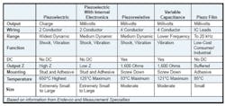
Table 1. compares the characteristics of accelerometers based on several different operating principles.
Table 1. Accelerometer Characteristics
Dynamic and Static Acceleration Response
One of the uses of an accelerometer is as an inclinometer. It's important in many applications to determine angular position. For example, in large cranes, pendulum-based inclinometers measure angular offset from the vertical. The acceleration of gravity causes a pendulum to hang vertically, and the inclinometer compares the position of the crane boom to the vertical datum. Clearly, this application requires good accuracy and a continuous output at low frequencies including DC, but high-frequency response is not a factor.
A moving-mass accelerometer also can be used as an inclinometer. Good sensor design ensures very little output from acceleration not in the intended direction. For example, the accelerometer in Figure 1 has a symmetrical construction that tends to cancel the effect of any motion not in the Z direction. However, the frequency response of a piezoelectric element does not extend to DC, a few Hertz being the lower limit in many accelerometers of this type. In contrast, sensors based on strain gages, variable capacitance, or LVDT principles correctly respond to the static acceleration of gravity and can be used as inclinometers.
In DC or nearly DC applications, an accelerometer's long-term gain and offset stability are critical. Several MEMS inclinometers from VTI Technologies have a total uncompensated start-up drift of about 1.0 mg, equivalent to 0.06 , that occurs largely within the first minute of use. In the Model SCA103T, compensation reduces this value to typically 0.002 . Noise ranges from 10 to 14 g/√Hz and is reduced by a factor of √2 in the SCA103T.
Freescale Semiconductor's Model MMA7260Q capacitive accelerometer also is used in angular position-sensing applications. However, according to Michelle Kelsey, an applications engineer at the company, in hand-held products, other sensor characteristics are more important than extreme accuracy.
This device is a member of the g-Select family of accelerometers, which has the capability to toggle among four different sensitivities. This feature can be used to monitor the tilt angle of a hand-held product that, in turn, would determine the speed and direction for scrolling through lists and menus. With g-Select,• she continued, the accelerometer can detect a larger number of motions, leading to increased user-interface enhancements.
One of the fastest growing sensor technologies is piezoelectric film or simply piezo film, a generic name for polyvinylidene fluoride, a polarized fluoropolymer with high piezo activity. Transducers based on this material have exceptional properties: frequency response from 0.001 Hz to 109 Hz, dynamic range from 10-8 to 106 psi, 10• higher output than piezo crystals for the same force input, high mechanical strength, and high mechanical stability. Applications include accelerometers but range from switches and microphones to piezo cables used as intrusion sensors around the perimeter of secure areas.
The extreme sensitivity is largely due to the format of the piezo film material. The low thickness of the film makes a very small cross-sectional area, and relatively small longitudinal forces create very large stresses within the material.1
Measurement Specialties produces the Model ACH-01 Piezo Film Accelerometer that responds to the motion of a proof mass acting to compress a section of film. This style of construction features a high resonant frequency and wide dynamic range. In another design, Model ACH-04-08-05, three segments of film are attached to mutually orthogonal beams, providing simultaneous outputs representing acceleration in the X, Y, and Z directions. The beam design is better suited to lower frequency applications.
The company also manufactures accelerometers using other technologies. Bob Arkell, product manager for the vibration sensors business group, said, The Model 52 is a miniature [piezoresistive MEMS-based] accelerometer designed for automotive side-impact testing. It is placed on a vehicle to measure the impact of a crash cart on a stationary test vehicle when the cart hits the driver's side at a velocity of approximately 30 km/h. The unit must have a very stable signal output and be able to withstand >2,000g acceleration. Further, a low profile and adhesive mounting are needed for correct placement in hard-to-reach places.
Two primary designs have evolved to meet the needs of the crash [test] industry: single cantilever and multiple cantilevers,• he continued. The single cantilever can be likened to a diving board while the multiple cantilever design is similar in concept to a trampoline. The use of multiple cantilevers ensures better transverse sensitivity, superior overshock protection in all three axes, and excellent transduction efficiency.
Piezoelectric accelerometers generate an output charge without requiring a power source. However, unless a very high temperature environment is involved, a unit with integral signal conditioning to provide a voltage output is much easier to work with. Piezo film devices directly generate an output voltage but also may contain buffer amplifiers to provide a low output impedance.
Piezoresistive sensors often are made from silicon, which exhibits a change in resistance when stressed. Such resistive elements are used in full or partial bridge circuits driven from an external power source. The piezoresistors may be integrated with interface circuitry or provided as a basic resistive bridge.
MEMS Accelerometers
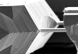
Surface-machined MEMS accelerometers are distinct from so-called bulk-machined devices that do not use standard semiconductor manufacturing processes. Bulk-machined devices have silicon elements, but they are supported on a glass substrate to which the silicon wafer was bonded. The elements are defined in the silicon wafer by doping and the unwanted parts of the wafer dissolved in acid. The doped areas dissolve very slowly, so after this procedure, they remain as separate parts of the MEMS device supported by the underlying glass substrate (Figure 2).
Figure 2. Example of Bulk-Machined Accelerometer Proof Mass And Supporting BeamsCourtesy of VTI Technologies
This technique has been used for several years; however, the resulting parts are up to 20• larger than surface-machined parts. Also, because the acid dissolution stage is not part of standard semiconductor processing, these parts cannot be manufactured in the quantities and at the cost associated with conventional CMOS ICs. So, why are bulk-machined parts still being produced?
A major reason is higher performance. As described by VTI Technologies• Ulf Merihein , the company's business development manager, Our technology provides real 3-D structures, not just thin films on top of silicon. It gives us flexibility in optimizing the accelerometer proof mass and capacitance dynamics for high performance. It also makes possible true 3-D sensing elements measuring in three directions. The relative capacitive change over the measuring range typically is 10 to 30%, making it relatively easy to provide a high signal-to-noise ratio and good accuracy.
VTI Technologies combines several technologies in the manufacture of their MEMS accelerometers. These include wet and dry etching, capping with wafer bonding and glass insulation, electrode feed through structures, and contacting for wire bonding and soldering.
One of the first commercial examples of a surface-machined MEMS accelerometer is the Analog Devices Model ADXL50, described in the company's Analog Dialog magazine in 1993. This device includes a differential capacitive accelerometer structure together with signal conditioning circuitry and measures acceleration from 0 to 50g with bandwidth from DC to 1 kHz.
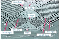
More recent MEMS accelerometers also use an interdigitated capacitive transducer as does the ADXL50 (Figure 3). However, that device operates in a force-balance control loop, and most modern devices operate open loop. The difference is significant and results in a typical ADXL50 nonlinearity of <0.2%.
Figure 3. Example of Surface-Machined AccelerometerCourtesy of Analog Devices
Many types of transducers use a force-balance concept. In an open-loop system, a transducer's operating point changes as the input signal changes. So, the accuracy and linearity of the output directly reflect those aspects of the transducer.
In a force-balance system, the output is applied to a negative feedback control loop and used to cancel the input signal. The net result is that the transducer operating point is nearly stationary. Accuracy and especially linearity are greatly enhanced because only a very small part of the transducer's transfer characteristic is being used.
CFX Technologies manufactures accelerometers using force-balance designs and also provides open-loop MEMS devices. Leo Stratton, the company president, said, We believe that MEMS devices eventually will displace the force-balance accelerometer in all applications except in the seismic arena, which requires very low noise. Our force-balance units measure acceleration from 10g to tens of g. MEMS devices are recommended for dynamic applications and where greater durability and low cost are required.
FOR MORE INFORMATION Analog DevicesiMEMS• Accelerometers www.rsleads.com/609ee-187CFX TechnologiesModel UM1 Force Balance Accelerometer www.rsleads.com/609ee-188CTCModel AC102-1A Piezoelectric Accelerometer www.rsleads.com/609ee-196EndevcoModel 7264D High Resonance Crash Accelerometer www.rsleads.com/609ee-189Freescale SemiconductorModel MMA7260Q Accelerometer www.rsleads.com/609ee-190Measurement SpecialtiesModel ACH-01 Piezo Film Accelerometer www.rsleads.com/609ee-191MEMSICModels MXD7210G&M Accelerometers www.rsleads.com/609ee-192MicroStrainG-Link• 2.4-GHz Wireless Accelerometer Node www.rsleads.com/609ee-193PCB PiezotronicsTEDS Accelerometers www.rsleads.com/609ee-194Silicon DesignsModel 2220 MEMS-based Accelerometer Module www.rsleads.com/609ee-195VTI TechnologiesSCA-3000 Series 3-Axis Accelerometers www.rsleads.com/609ee-197In the ADXL50, 42 fingers approximately 2 m wide and more than 50 m long are attached to the central mass and interdigitate with similar fingers fixed to the substrate. The fixed fingers, really capacitor plates, are electrically connected to form differential capacitors in relation to the central, movable, plates. In other words, there are two capacitances being measured: one increases when the moveable mass is deflected a certain direction, and the other decreases for the same direction of motion. The total capacitance of the 42-plate capacitor is 0.1 pF.
One set of fixed plates is biased at 0.2 V and the other at 3.4 V. The moving plates are nominally at 1.8 V, the midpoint. When the moveable plates deflect in response to an acceleration, a feedback signal is applied to oppose their motion.
In the 1996 ADXL150 device, the interdigitated design was refined to give much lower noise and power consumption. In addition, by limiting full-scale travel to only 1.5% of the gap between capacitor fingers, this device retained good linearity in a simple open-loop configuration. A separate set of self-test fingers allowed the entire measurement channel to be exercised in response to self-test driven motion.
This last point is an important one in safety applications such as automotive air-bag deployment. When a modern car is turned on, a power-up sequence is initiated in which, among other things, the air-bag accelerometers are tested. The ADXL150 actually produces movement similar to that experienced in normal operation and senses and processes that movement, providing a comprehensive self test. Both the ADXL50 and ADXL150 have been replaced by more recently introduced products in the iMEMS• range.
The MEMS manufacturing process also can be used to produce less conventional types of devices. For example, MEMSIC makes an accelerometer based on the distribution of heat through a small, trapped volume of gas. Acceleration of the device changes the density of gas locally within its chamber, causing the gas temperature around a central heater to vary. Thermocouples sense the temperature differences, which are converted to an acceleration value.
Unless you consider the gas molecules, MEMSIC's claim of no moving parts is true. Having fewer moving parts obviously improves reliability, but in surface-machined MEMS devices, no moving parts means that manufacturing is greatly simplified. When independent elements of a MEMS device are released from the substrate, it's possible for the elements to stick to it instead of moving freely. This is called stiction and, depending on the exact process used, can be a big problem in MEMS manufacturing.
In contrast, Endevco has introduced the piezoresistive Model 7264D High Resonance Crash Accelerometer with a resonant frequency above 40,000 Hz and a weight of only 1 gm. Stephen Bill, with the company's application support services, explained, Automotive crash test events typically involve extremely short duration shock-pulses, sometimes from hard metal-to-metal contact or mechanical fracture that may excite resonances in a sensor. With its high-frequency response, the 7264D eliminates phase shifts and saturation that can produce a temporary shift in the output signal. Further, an undamped response avoids confusion that can result from monitoring a test with a number of sensors having different damping coefficients.
Damping can be important, especially in low-frequency applications such as flight tests, vibration monitoring and analysis, machine control, robotics, and instrumentation. The Model 2241 MEMS-based accelerometer module, a low-frequency version of the Model 2220, is typical of the product range produced by Silicon Designs and is nitrogen damped with a DC to 250-Hz bandwidth. The module contains a sealed micromachined capacitive sense element, an integrated sense amplifier, and differential output stages. This device is unusual in having a hermetically sealed titanium case, making it fully waterproof.
The Model 2241-010, a 10g full-scale version, has 400-mV/g differential sensitivity and typical 10- g/√ Hz rms noise and 0.3% span nonlinearity. The device operates on 9 to 32 VDC, draws a maximum of 14 mA, and weighs 10 gm.
Summary
A wide range of conventional and MEMS-based accelerometers exists including special-purpose devices that emphasize factors such as ruggedness, small size, accuracy, stability, and cost. Because accelerometers address so many different applications, development of new technologies and enhancements to existing ones continue apace.
As an example of an enhancement, consider the addition of local nonvolatile calibration storage. Generically, this is termed a transducer electronic data sheet or TEDS and described by the IEEE Smart Transducer Interface standard.
A few details were given by PCB Piezotronics• Mr. Aszkler. This standard defines the hardware and communications protocol for interfacing a sensor onto a network as well as the architecture and protocol for compiling and addressing nonvolatile memory embedded within an analog sensor.
TEDS allows the user to identify specific sensors within a large channel group or determine output from different sensors at multiple locations very easily. In addition,• he continued, it provides the user with information about the particular sensor, such as model number, serial number, calibration date, and other technical specifications. Sensitivity specifications from calibration reports can be read through TEDS and compensated for so that the data acquisition system using the sensor can normalize output signals faster and reduce setup time.
A further consideration in the use of accelerometers is the difficulty of connecting many sensors attached to a large structure. The wiring, connectors, and special interfacing that may be required in a data acquisition system all add complexity and cost. One possible solution is the Agile-Link• range of wireless sensors produced by MicroStrain.
The G-Link• 2.4-GHz Wireless Accelerometer Node features MEMS-based measurement in three dimensions over a 2g or 10g range with a 500g shock limit. In addition, 1-Mword of onboard storage, a 12-b ADC, and programmable data sampling are built in. Data is transferred to a host PC via the IEEE 802.15.4 RF data packet standard, requiring five minutes to download the full memory. The complete device weighs 46 gm.
Reference
1. Piezo Film Sensors Technical Manual,• Measurement Specialties, 2006.
