The high-speed serial interface signals supporting today's computer and communications systems are too fast for most general-purpose test equipment. For example, PCI Express operates at a 2.5-GHz bit rate, equivalent to a 1.25-GHz fundamental frequency. For accurate measurements, oscilloscope manufacturers recommend that a scope's bandwidth should be at least as high as a digital signal's fifth harmonic or 6.25 GHz in this case.
Although the average scope bandwidth has been increasing over the years, today it's far closer to 1 GHz than 6.25. And, PCI Express already has been surpassed by PCI Express 2.0 at 5 Gb/s, fully buffered DIMM running at 4.8 Gb/s, and fibre channel at 4.25 Gb/s. In all three of these examples, bandwidth greater than 10 GHz is required to include the fifth harmonic of the fundamental frequency.
Recently, major scope manufacturers have introduced instruments with bandwidths from 15 GHz to 20 GHz. Nevertheless, it's unlikely that a huge used-equipment market suddenly will develop based on thousands of abandoned lower bandwidth scopes.
A more probable outcome is that engineers will use high-bandwidth sampling scopes. The new DSOs only are necessary if single-shot fast transients must be investigated. Otherwise, most serial interface characterization can be accomplished with repetitive sampling scopes.
Sampling Scopes
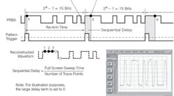
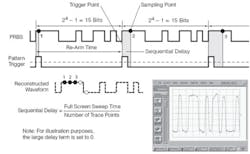
Traditional sampling scopes require a trigger that is synchronous with a repetitive signal. At each successive trigger, the scope samples the signal at a slightly later time. For example, if you wanted to examine a 1-ns long portion of a signal and your scope could display 1,000 points horizontally, each sample would be delayed an additional 1 ps from the trigger as shown in Figure 1. In this way, a very detailed view of the signal is built up, equivalent to an extremely high sampling rate, much higher than even that of the newest 50-GS/s DSO.
Figure 1. Sampling Process for a Pattern Waveform
Courtesy of Agilent Technologies
Sampling scopes boast bandwidths up to 80 GHz or more and 14-b vertical resolution. The trade-off made to achieve these impressive specs is a sampling rate typically less than 1 MHz. It's important to understand that the built-up picture is not an expanded version of a single-shot DSO acquisition: Rather, it contains elements of thousands of signal repetitions. This method of operation results in many subtle implications. Nevertheless, if you can work with a repetitive signal, you may have access to much greater fidelity in time and amplitude than achievable by other means.
Triggering
There is a finite time delay between the instant a trigger occurs at the scope's front-panel connector and when the corresponding sample is taken. For example, in the Agilent Technologies Model 86100C Infiniium Digital Communications Analyzer (DCA), this delay is approximately 24 ns. Here the word approximately means that the minimum trigger-to-sample delay is not exactly 24.000 ns although its actual value has less than 100-fs uncertainty. LeCroy lists a 12-ns delay for its WaveExpert• Series of sampling scopes.
Variation in the trigger timing relative to the input signal translates directly into jitter. The 86100C has a fastest time-base setting of 2 ps/div or 500 fs/div with the 86107A precision time-base reference module. At these speeds, it can be very difficult to maintain low jitter using a separate trigger signal. To put things in perspective, an electrical signal in a typical coaxial cable travels about 0.025 mm in 100 fs. This distance is equivalent to the change in length of a 1-m cable caused by a 2 C temperature change.
Obviously, sampling scopes are successfully used with separate trigger sources. The point is simply that accurately measuring subpicosecond effects involves many types of errors that usually are ignored for nanosecond-scale signals. Unless you can account for these errors or in some way minimize them, few digits of the high-precision measurements your scope displays will have significance.
Some sampling scopes can develop a pattern-based trigger internally. For example, the 86100C enhanced trigger option provides the PatternLock facility. PatternLock automatically detects the pattern length, data rate, and clock rate and produces a stable trigger at a user-selectable position within the pattern.
This feature has required changes to the traditional sampling-scope architecture that provide additional related benefits. For example, by taking samples sequentially through a data pattern, the time relationship among a group of samples is maintained. This means that should an anomaly be found in an eye diagram, the effects of specific bit transitions can be investigated.
The Tektronix Digital Serial Analyzer Sampling Oscilloscope Model DSA8200, when fitted with the Model 80A06 PatternSync Module, also can develop a stable trigger from a repeating data pattern. The 80A06 is a programmable counter that accepts clock rates from 150 MHz to 12.5 GHz. It divides the clock rate by a number from two to 223 to produce a stable trigger synchronized to the data pattern.
By using the 80A06 together with the FrameScan• acquisition mode, you can repetitively acquire selected bits within the data pattern. FrameScan automatically advances the trigger location to the next bit position after the acquisition process has been completed. Alternatively, you can elect to capture data relating to only one bit position. FrameScan data can be averaged.
One complete data pattern is termed a frame and a bit within the pattern a subframe. To acquire successive subframes, the scope's time base must be set to units of bits rather than time. In addition, you must enter the data rate, pattern length, and data-to-clock ratio or select the corresponding auto-sync options so that the module can automatically detect these parameter values. Because there is no unique beginning to a repeating pattern, you must enter a relative trigger bit value to advance or retard the effective trigger point within the pattern.
LeCroy's WaveExpert Model NRO 9000 offers conventional sequential sampling as well as coherent interleaved sampling (CIS). Because CIS is a new acquisition mode that operates differently than both a traditional sampling scope and a DSO, LeCroy coined the term near real-time oscilloscope (NRO). Sampling scopes generally have very short acquisition memories when compared to the megabytes of DSOs. With CIS, sampling rates are from one to two orders of magnitude faster, and longer memories are more practical.
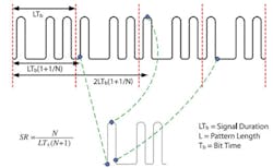
Traditional coherent sampling establishes a rate relative to the repetition rate of the data pattern (Figure 2a). For example, if a data pattern repeated every eight bits or unit intervals (UIs), the display required 1,000 points, and all eight UIs were to be shown, 125 samples per UI would be needed. The incremental delay between sampling points would be adjusted so the successive positions of the 1,000 samples progressed evenly through the eight UI data pattern.
Figure 2a. Coherent Sampling Data Acquired by Locking to the Data Pattern Rate
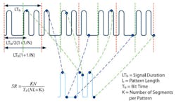
CIS works in the same way as coherent sampling but subdivides the data pattern to achieve a higher sampling rate as shown in Figure 2b. Because of this subdivision, successive samples no longer are in the correct time order and must be re-ordered post-acquisition.
Figure 2b. CIS Acquired Samples at a Fixed Rate by Dividing the Data Pattern Into Segments and Reordering Samples With Respect to Their Position in the Segment
Courtesy of LeCroy
CIS and coherent sampling use a PLL to synchronize the sampling clock rate to the data rate. This is a different mode of operation than FrameScan or PatternLock that reference the positions of successive samples to a pattern trigger. CIS is controlled by a samples/UI parameter while FrameScan and PatternLock acquisitions run at fixed, selectable time-base rates.
A general consideration that applies to all sampling scopes concerns using subrate or divided clocks to generate eye diagrams. It is common for clocks to run at some integer division of the data rate. For example, a 40-Gb/s data stream may be developed by multiplexing four 10-Gb/s streams so the available clock rate would be 10 GS/s.
If the clock is used as the trigger, an eye diagram will be formed that shows all possible combinations of data transitions. At least, that's the objective. However, if the length of a repetitive data pattern is directly related to the subrate clock, only a fraction of the pattern may be sampled. In the 40-Gb/s data and 10-GS/s clock example, if the pattern is 20 b long, the same 5 b will be sampled by the 10-GS/s clock. Only 25% of the data transitions will make up the eye diagram. To avoid this problem, the pattern length must not be evenly divisible by the clock division factor, four in this case.
Clock Recovery
One way that clock-to-data skew and uncertainty have been controlled is to embed the clock within the data stream. There is only one signal so the clock-to-data skew is, by definition, zero. On the other hand, the clock must be recovered from the data stream, usually by using a PLL (Figure 3).
Figure 3. Clock Recovery Module Block DiagramCourtesy of Agilent Technologies
In theory, it makes sense to recover the clock using a PLL with characteristics similar to those of the actual clock/data receiver (CDR) that will be used in the system. By matching the PLL to the CDR loop bandwidth and related parameters such as rate of pass-band roll off, the recovered clock will have the same amount of jitter as the clock that will be used in the real system. Nevertheless, there are reasons to independently control the instrumentation PLL bandwidth.
For example, if the loop bandwidth is very high, the loop will follow even high-frequency jitter so the recovered clock will have most of the same jitter that is affecting the data. If you trigger a sampling scope with this type of recovered clock, because jitter is causing the trigger and data to move by the same amount and in the same direction, the acquired signal will be very clean. This mode of clock recovery would be useful for examining rise/fall times and pulse widths without the added uncertainty caused by jitter.
On the other hand, a very narrow loop bandwidth causes the PLL to ignore most of the data jitter, producing a very stable clock. In this case, almost all the data jitter will be apparent in the acquired signal because there is little clock jitter. When viewed as part of the overall signal-acquisition process, clock recovery PLL loop bandwidth has a converse effect: A wide loop bandwidth acts like a low-pass narrowband acquisition filter while a narrow loop bandwidth acts like a wideband acquisition filter.
An example of this type of PLL effect is found in LeCroy's description of the CDR-E135 Electrical Clock Recovery Module. With the extended frequency range option, data rates from 622 Mb/s to 13.5 Gb/s are accepted. The unit is specified with a 6-MHz PLL loop bandwidth and recovers a clock with typically no more than 500-fs rms jitter.
The important point is a data sheet comment about the action of the CIS PLL when used with this module: The recovered clock is used by the [WaveExpert] time base as a reference, and the action of the PLL in the CIS time base removes any residual jitter in the recovered clock, allowing the time-base jitter to be as low as 250 fs rms when the high-stability CIS time-base option is present in the oscilloscope (HCIS).
The data pattern transition density also affects PLL gain and loop bandwidth. Transition density is defined as the ratio of the number of transitions that actually take place to the number that could. A 010101 pattern is changing on every bit position so it has a 100% transition density. A 001100 pattern has only a 50% transition density. This effect can be important, and some standards specify the pattern used for testing so the test is repeatable.
Many serial data specifications call for the use of a golden PLL, one in which the loop bandwidth is matched to that of the standard. For example, a multirate clock recovery option is available for Wavecrest SIA instruments. For a wide range of serial communications standards with bit rates from 1.0625 Gb/s to 4.25 Gb/s, the bandwidth of this option is the bit rate divided by 1,667. It also is common for some standards to specify bit rate/2,500. In these cases, the PLL loop bandwidth is set by the data rate so you are limited to acquiring data within the parameters of particular standards.
Agilent's Model 83496A/B Series of clock recovery modules features a continuous range of input data rates from 50 Mb/s to 13.5 Gb/s as well as continuously adjustable loop bandwidth from 15 kHz to 10 MHz. The Tektronix Model 80A07 Electrical Clock Recovery Module provides a large number of clock division ratios between 1 to 648, continuously variable data rates from 100 Mb/s to 12.5 Gb/s, and continuously tunable loop bandwidth from 100 kHz to 12 MHz. Either module can function as a golden PLL.
Enhanced Accuracy Clocking
Time-base jitter less than 1 ps is impressive, but can you achieve better? Yes you can, and reference phase measurement is the key. This technique recently was recommended by the ITU in document O.172 as an accurate way to measure jitter. Although not new, the approach has benefited from improved components and implementation.
A Tektronix application note describes the operation of the Model 82A04 Phase-Reference Module.1 At the heart of the module are two samplers that are driven simultaneously. One samples the input data and the other a user-supplied synchronous clock. Typically, to achieve the lowest possible uncertainty, this clock would be generated by a highly stable, low-noise reference oscillator such as an RF synthesizer.
Before the module can be used to acquire signals, the reference clock must be characterized. A total of 250,000 clock cycles are sampled by a free-running asynchronous strobe and the information used to build a voltage-to-phase lookup table. Using this information, the module can convert a sample of the reference clock to an equivalent clock phase. Ideally, the clock should be a perfect sinusoid, but the module is designed to cope with distorted clocks more often seen in practice. Given a user-supplied reference frequency, an equivalent time can be computed.
Because the data and reference clock samplers are simultaneously strobed, a precise clock phase is associated with each data sample. In a free-running mode, the data samples are displayed relative to one complete 0-to-2π reference cycle. The eye diagram produced differs from that which the scope ordinarily would display without the phase reference module because each data point has been corrected according to the phase measurement.
A triggered mode of operation also is supported by the 82A04. In this case, the oscilloscope performs its usual sequential sampling action synchronized to a repetitive trigger. The data and reference clock are simultaneously sampled at the time the oscilloscope samples.
If the reference clock sampler is ignored for the moment, this mode mimics that of a traditional sampling scope except that the actual data sampling is performed by the 82A04. Samples are taken relative to the trigger just as they would be under normal sampling-scope operation. The difference is that the reference clock sampler is providing a separate, very accurate timing of the scope time base.
In effect, each sample is tagged with the integer number of reference clock cycles and the phase of the cycle in which the data was sampled. The reference clock oscillator is being used to provide precise sample timing with greater accuracy than the scope time base. This additional information allows the data to be displayed avoiding scope time-base nonlinearities or jitter. The advantage provided depends on the degree to which the reference clock is more stable and accurate than the scope time base.
Another issue related to clock recovery is jitter bandwidth. Because of a sampling scope's several nanosecond delay from trigger to sample point, the effect of high-frequency jitter on the sampled data may be very different from its effect on the trigger some number of nanoseconds earlier. Worst case, if the jitter has a component with a period similar to the trigger-to-sample delay, the data can be acquired with twice the actual jitter.
The reference clock measurement approach used in the Tektronix 82A04 Module avoids most of this problem by simultaneously strobing the data and reference sampling gates. Nevertheless, even in this technique, the small mismatch between the sampling gates themselves contributes similar types of errors albeit at much higher frequency.
Another technique that is used in some clock recovery modules is to provide an approximately equal delay in the data path. For example, in the Agilent 83496A Optical Clock Recovery Option, a length of optical fiber is built in to align the trigger event and sampling instant. Even though the compensation will not be exact, it considerably minimizes the problem of constructive interference that otherwise could exist.
Conclusion
As the speed of serial data communications links continues to increase, distinctions between analog and digital technologies that are obvious at low frequencies become blurred. Digital modulation schemes no longer produce only a fixed set of allowed phase/magnitude constellation points, for example. Rather, each ideal position has grown in width and height because of noise, crosstalk, phase offset, gain errors, and various varieties of jitter. What kinds of test tools best address these analog factors?
DSOs, the largest segment of the oscilloscope market by sales, continue to advance the art of digitization while also achieving ever-greater bandwidths. Nevertheless, performance is only just adequate for today's serial data speeds. To make the best measurements possible on high-speed signals, would you voluntarily choose to include only the fifth harmonic and limit yourself to 8-b resolution?
Sampling scopes have long addressed the acquisition of high-speed signals but can be hard to use and slow to display the desired waveform. New digital techniques teamed with the sampling scope's high bandwidth and resolution have resulted in instruments with very attractive features. And, because of automated functions such as Agilent's PatternLock and LeCroy's CIS, complex acquisition modes are greatly simplified.
In addition, sampling scopes recently have enjoyed increased interest as an alternative to RF network analyzers. Time-domain reflectometry, making full use of the sampling scope's high resolution in both the amplitude and time axes, has become a growth market. S-parameters determined via scope-based TDR typically correlate to within a few percent of network analyzer results. For many non-RF engineers, the network analyzer's slightly better performance is easily offset by its complex calibration, high cost, and unfamiliar operation.
Today's sampling scopes are not the same instruments that your grandfather used, as the saying goes. They continue to exceed the bandwidth and sampling rate of the best DSOs by a large margin but have gained many new capabilities as well, such as jitter measurement and analysis. Why not evaluate a sampling scope before starting your next serial data project? You may be pleasantly surprised.
Reference
1. Ultra-Low Jitter Performance With Phase-Reference Module 82A04 and TDS/CSA8200 Sampling Oscilloscope,• Tektronix, Application Note, 2004.


