Boundary Scan Tests Ensure Midplane Quality
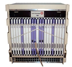
At Alcatel-Lucent, we test chassis-level products that provide 42 board slots on a midplane, essentially a passive backplane that accepts boards on its front and rear sides. Thirty-four of those slots accommodate many types of boards.
Typically, we fill all empty slots to perform functional slot testing in addition to tests we run with only the boards designed for integration into a customer's equipment. This type of functional slot testing verifies all chassis slots work properly, and it supplements tests we run to ensure the customer's plug-in boards meet specifications.
Our team discussed ways to reduce the time needed to verify a chassis and homed in on the time used for the functional slot testing, which varies depending on the board configurations. We decided to add a thorough post-assembly interconnect test at the contractor's site where midplanes are assembled into our chassis. This step also would reduce the time needed to return a defective chassis to the contractor.
We could purchase a commercial tester and design appropriate paddleboards, or we could design paddleboards that would connect to a boundary scan tester. It cost less to take the latter route, and we avoided the need to attach a commercial tester to as many as 20,000 connector pins.
We already used a boundary scan test box for board-level assemblies, and this technique requires only a five-signal interface cable. Advantages of the boundary scan approach included reduced cost, simplicity, and the capability to move the test process from facility to facility. Disadvantages included the need for engineers to develop and support boundary scan tests and the uncertainty that existing boundary scan hardware and software could handle such a large project.
Because neither our group nor our midplane manufacturer had extra paddleboard testers available and because we value manufacturing-location flexibility, we chose the boundary scan approach. Before starting the boundary scan design, we consulted with the technical support group at JTAG Technologies to verify nothing would prevent us from running existing test-generation software for our proposed design, which combined 42 paddleboards and the midplane. We previously used JTAG Technologies• hardware and software for single and multiboard tests and continued to use it for this project.
Paddleboard Design
The midplane tests required three front-loaded paddleboard designs and two rear-loaded paddleboard designs to provide test coverage for all slots through a multidrop boundary scan test arrangement. Three of these five designs included hardware options that let a paddleboard operate in slots with slightly different connections.
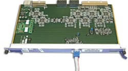
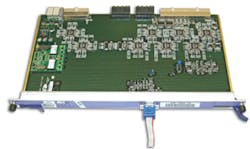
The same circuitry exists on all boards, although connectors vary depending on the slot a board will occupy. The paddleboard that connects to the external boundary scan tester provides an external five-wire interface through a DB-9 connector as shown on the front panel of the board in Figure 1. A slightly smaller board offers similar functions less the tester interface but plugs into the rear of the midplane.
Because we needed 42 test boards, we based our scan-chain designs on the Texas Instruments 10-b 74LVT8996 Test Access Port (TAP) Transceiver. For each TAP transceiver, we took advantage of five address signals already present at each midplane slot.
A customer's system normally would use these signals to identify slots in a chassis. To reduce noise, our design buffers the boundary scan signals as they enter the midplane.
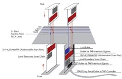
We connected the test mode select (TMS), test data in (TDI), test data out (TDO), and test reset (TRST) boundary scan signals to conductors that ran to each board slot on the midplane. But we located the boundary scan entry-point paddleboard in a slot that provides a separate TCLK clock signal to each pair of front and rear cards (Figure 2). This approach minimized noise on the TCLK lines.
We could have taken a traditional approach and placed the TCLK connections on a single conductor. But with this type of signal distribution, we anticipated signal-integrity problems at or above our 1-MHz TCLK target frequency.
An LED on each paddleboard indicates a match between a board's slot address and the address provided by the boundary scan test. This LED proves particularly useful when technicians must debug infrastructure failures on defective units. They can easily determine which boards the tester has addressed.
After we completed the paddleboard circuit designs and before we laid out PCBs, we used JTAG Technologies• software tools to run a test to ensure the netlists would combine properly and the software could generate the infrastructure and interconnect tests. Working together with JTAG Technologies, we overcame a few minor issues and successfully completed the test case.
To test our hardware, we first built the paddleboard that included the boundary scan interface. This circuit, common to all the other paddleboard designs, worked properly, so we implemented the additional four paddleboard designs.
Preliminary Tests
To simplify the project, we developed initial boundary scan tests for individual front boards and then for each pair of front and rear cards in the chassis (Figure 3). The 21 tests, one per paddleboard pair, required us to combine 21 groups of three netlists, two for the paddleboards and one for the midplane, to come up with necessary netlists for each front and rear pair in the chassis. By the time all of these combinations worked, we had identified and cured most minor problems that could affect test and debug operations.
After we had verified the proper operation of all paddleboards, we created and debugged tests for the combination of 42 paddleboards and the midplane. This process, including the four days spent waiting for the test generator to complete the interconnect test, went smoothly. We expected a long wait based on the test case performed earlier, before we had any hardware in hand. Those runs took about seven days on a slower computer, but that long time is not representative of most boundary scan tests.
Test the System
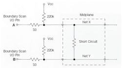
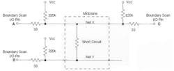
To test the capability of our hardware and software to detect chassis failures, we populated a known-good chassis with paddleboards and placed a shorting wire between two signal paths, or nets, on the midplane. As shown in Figure 4a, the chosen nets, X and Y, each connected to a single three-cell boundary scan I/O pin, pins A and B. Unfortunately, the interconnect test did not detect the short circuit.
The test generator had provided patterns that drove all nets on every test step. But, the series termination resistors we chose to use on all boundary scan pins let pin A on net X both drive and sense a logic high while simultaneously pin B on net Y drove and sensed a logic low on its side of the short circuit. If at least one of the short-circuited nets had two boundary scan-capable I/O pins, the tester would have detected a problem because only one pin on each net may drive the net while the other pin senses the state of the net.
As a result, we could not detect a short circuit between two nets when each net connects to only a single boundary scan I/O pin. Fortunately, nearly all nets in our system have at least two I/O pins because nearly all pins in the midplane go through the midplane to corresponding I/O pins on both front and rear paddleboards or through midplane nets to I/O pins at other connector pins.
Net X in Figure 4b, for example, connects to both front and rear paddleboards. When we installed a shorting wire between any midplane conductors with two or more I/O pins on each conductor, we produced a test failure and a correct diagnosis.
We discovered an additional case in which a chassis that passed our boundary scan test failed during its functional tests. To find out why, we applied old-fashioned troubleshooting techniques and found a net that did not go to as high a voltage as we had expected. An 80-Ω short between two nets in the midplane caused the problem.
The two nets involved in this fault each had more than one driver. But, the high-impedance short between nets still let each net properly track only the drivers on that net. (Our automatically generated interconnect tests always drive all nets.) After some analysis, we decided to create manually generated tests for each pair of front and rear paddleboards.
The manually generated shorts tests would drive one net low while relying on high-resistance pull-up resistors on other nets to be sensed as a high. Instead of using the combined netlist for all 42 paddleboards and the midplanes, we created 21 tests, one for each pair of paddleboards and the midplane. These added tests had several advantages that let them:● Detect high-impedance shorts.● Find shorts on nets that only had a single boundary scan device.● Diagnose nearly all possible chassis faults. These 21 tests worked so well that we included them in the sequence of tests used for the boundary scan chassis test prior to running the overall interconnect test.We currently use one of our two testers at an outside manufacturing facility that assembles and now tests our chassis. This added test on a fully assembled chassis gives us confidence that chassis-assembly operations introduced no faults. Our second boundary scan chassis tester operates at our repair depot.
Test Times
With 42 paddleboards, each having 500 to 700 connections to the midplane, the test time for the interconnect comes to about 2 seconds for a 4-MHz clock. Short-circuit tests take about 2 seconds for each of the 21 front and rear connector pairs in a midplane.
Overall tests for a good chassis take less than a minute of run time. We could have increased the boundary scan clock frequency to 10 MHz by placing the TAP closer to the midplane and using a 12-inch cable. But for convenience, we chose to use a 5-foot cable and the 4-MHz clock. The time needed to run the tests amounts to only a small part of the overall 15 minutes it takes to carefully install the 42 boards and mate the single boundary scan cable to the DB-9 connector and execute the test procedure.
It takes our test system only a few seconds to find and display any infrastructure errors or errors from the 21 shorts tests, one test per paddleboard pair. The present system needs 2 seconds to run the Interconnect test on a good unit, but if a failure occurs, it takes about 6 minutes to run diagnostic software and identify a simple short or open. Given the long diagnosis time, we run the overall interconnect test only after a system passes the faster short-circuit tests.
Boundary scan techniques that run production tests and debug a midplane take place in much the same way as tests we apply to any single PCB. Our new test system lets engineers and technicians apply the skills and training they already have acquired. Training and debugging experiences emphasize the use of the faster shorts tests where possible. As a result, test system users should rarely have to wait for a 6-minute or longer automated diagnosis.
About the Author
Bill Philbrook works for Alcatel-Lucent as a senior test engineer where he prepares and maintains boundary scan tests, performs testability reviews, and carries out component investigations and qualifications. He has enjoyed electronics as a hobby and received a B.S.E.E. from Worcester Polytechnic Institute. Alcatel-Lucent, 734 Forest St., Marlborough, MA 01752, 508-804-8243; e-mail: [email protected]
FOR MORE INFORMATION
on boundary scan support services
at JTAG Technologies
www.rsleads.com/704ee-185
