According to a Tyco Electronics application note, “Silver cadmium oxide contacts have long been used for switching loads that produce a high energy arc. Silver cadmium oxide contacts are less electrically conductive than fine silver contacts, but have superior resistance to material transfer and material loss due to arcing. They do exhibit greater interface resistance between mated contacts and, like fine silver contacts, the silver in this alloy will oxidize and sulfate. Therefore, an arc is necessary to keep these contacts clean.”1
For low-level signals, gold-plated contacts are the best choice because sulfidation is minimal and a good electrical contact is made when the relay is closed. On the other hand, gold soon boils off contacts subjected to arcing so signal amplitude must be less than 15 V.
Tungsten often is used for very high-voltage switching contacts because its 3,380°C melting temperature provides good arc-erosion resistance. But, as the Tyco reference explains, “Tungsten may develop troublesome oxide films, especially when used as the anode contact in some DC applications. Therefore, tungsten is often used as the cathode contact, and a palladium alloy used as the anode contact. Such a combination also minimizes contact interface resistance and material transfer.”
Instead of electromechanical relays, a FET-based design may be more suitable. Even tiny reed relays are relatively slow to switch compared to electronic speeds. If your application must switch at a high rate and have virtually unlimited life, FET switches could be the answer. The largest drawbacks of FET switches are their high ON resistance and limited current handling capability. This may sound like a good idea, but a closer look at the technical details quickly highlights several problems. Relay contacts made from silver, gold-plated silver, silver oxide, and tungsten are used depending on the characteristics of the signals to be switched.
RF and Microwave Considerations
At frequencies where transmission lines are used, switches no longer can be adequately described just by their power-, voltage-, and current-handling capabilities. In addition, the frequency range, isolation, insertion loss, and voltage standing wave ratio (VSWR) become important. These parameters are affected by contact material and size but greatly depend on the overall relay design. Specially constructed coaxial relays look very different from DC relays because of their high-frequency performance.
With an appropriate drive circuit, P-type intrinsic N-type (PIN) diodes act like a pure low resistance to RF signals and have been used for decades to switch frequencies greater than 1 MHz. Gallium arsenide (GaAs) FET and monolithic switches were developed more recently. Their speed and longevity advantages are similar to low-frequency FET technology but so too are their drawbacks such as higher ON resistance. Switch refinement continues with the benefit of colocation on the same die as related circuitry.
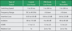
A Dow-Key Microwave switch selection guide lists the parameters shown in Table 1 for coaxial, PIN diode, and GaAs monolithic switches. It’s likely that the GaAs column values have improved somewhat since the guide was published. In contrast, coaxial and PIN diode switches both are mature technologies and continue to be the most commonly used.2
Table 1. RF and Microwave Switch Technology Comparison
Courtesy of Dow-Key Microwave
As the table shows, nothing compares to an electromechanical coaxial relay for frequency range, insertion loss, and isolation. PIN diode switches have the advantage of size when the components are treated as part of a larger circuit board and, being electronic, longevity and speed.
Agilent Technologies’ Boon-Khim Tan, operations manager test accessories operation, highlighted the differences among the electromechanical, PIN diode, and FET switches the company offers. “Electromechanical switches demonstrate low loss, superior distortion performance, and high power-handling capability but suffer from slow switching speed and a finite life. Solid-state PIN switches are used for applications requiring fast switching speed but have video feedthru that makes them unsuitable for testing sensitive devices,” he said. “FET switches have very low video feedthru but slower switching speed and higher loss compared to PIN switches.”
Mr. Tan’s comment about video feedthru is another way of saying that the switch control signal corrupts the output. Generally, it’s the edges of the switch control gate that feed through capacitively and add to the actual RF being switched. This causes distortion to the leading and trailing edges of an RF burst. If the edge speed of the control signal is sufficiently fast compared to the RF frequency, the resulting interference can be filtered. On the other hand, the control signal feedthru amplitude can be relatively large, which is the reason for Mr. Tan’s caution with regard to sensitive devices.
Relay ReliabilityRelay contact life is most affected by arcing. Different contact materials arc at a range of minimum voltages between about 10 V and 15 V, so one way to avoid the problem is to limit the voltage levels being switched. If this is impractical, try to synchronize signal generation with relay operation.The term cold switching describes switching a zero-level signal. After the switching
action has completed, the signal level can be returned to the required value.
For example, as part of a test setup, a signal generator could be driving an amplifier with the output selectively distributed to several loads through a relay network. Cold switching could be achieved by programming the generator to output zero volts, then selecting the appropriate relay path, and finally programming the generator to output the full-amplitude signal. At least an order of magnitude difference in operational life typically results from cold vs. hot switching.
Relay cycle counting is related to reliability. Relays eventually wear out and must be replaced when contact resistance has increased beyond a certain limit, usually not because something actually broke in the mechanism. As logical as this sounds, once a relay has been connected as part of a switching system, it’s disruptive to isolate it to measure the contact resistance and simply impractical to do so for hundreds of relays in a large multiplexer or matrix. Pickering Interfaces makes the argument that cycle counting is an indirect and potentially misleading way to determine when a relay should be replaced.
According to David Owen, business development manager at the company, “…relay operation counting…[doesn’t] take account of the switching load conditions—factors that have an impact of three or four orders of magnitude on relay life. BIRST [built-in relay self-test] will help avoid unnecessary service operations and help guarantee peace of mind in terms of test system reliability.”
The datasheet for a BIRST-equipped relay matrix states, “No supporting test equipment is required to run a BIRST test; simply disconnect the UUT from the module’s user connector, launch the supplied BIRST application software, and the tool will run a diagnostic test that will find all relays with contacts welded closed or with high (open) contact resistance. It makes it simple for systems integrators to diagnose the cause of switching failures in a system.”
At present, BIRST capability is built into a number of PXI low-frequency relay-based matrices such as the 40-527 64×2 matrix with 15-MHz bandwidth. It is not clear if this technology is compatible with the company’s RF and microwave switching products although Mr. Owen’s comments about the inadequacies of cycle counting and the need to account for the effects of the load also apply to high-frequency relays.
Switch Modules
As in low-frequency applications, RF and microwave switching must be integrated with the rest of the test system. For PXI and VXI systems, this often is done by choosing switch modules with the same form factor as the majority of the test instrumentation.
Travis White, the company’s product manager-precision measurements and switching, said, “NI switches based on the PXI platform offer on-board hardware scanning and integrated triggering, which enable RF engineers to significantly reduce test times. A scan-list can be loaded onto PXI switch hardware and successive routes actuated based on hardware triggers from other PXI instruments such as RF vector signal analyzers and generators or a variety of other RF, DC, and digital instrumentation.
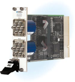
Figure 1. NI PXI-2596 Dual 6×1 MultiplexerCourtesy of National Instruments
“Because this whole process is hardware-timed, all software delays are eliminated, thereby saving precious milliseconds on each test point—over thousands of points, test times can be substantially reduced,” he continued. “We’ve seen this technique provide the most benefit to engineers working in production test environments where RF generators and analyzers must generate the same sweeps on many devices under test in as short a time as possible.”
NI supports switch configuration and management through the company’s Switch Executive software program. It allows engineers to graphically configure large route groups spanning multiple switch modules. The routes can be easily validated and a group of multiple relay closures programmed with a single function call.
Dow-Key Microwave provides a large number of microwave components as well as a few PXI modular switches. One of these, Model 14F3S-1/4×4 is an 18-GHz reconfigurable bidirectional nonblocking matrix with four inputs and four outputs. It occupies four PXI chassis slots and comes with five external semirigid cables interconnecting appropriate ports. By removing and/or rearranging the cables, the module can be reconfigured as separate sets of SPDT, DPDT, and SP4T switches.
The relays have gold-plated beryllium copper contacts, switch in a maximum of 25 ms, and under cold-switching conditions provide a 1E6-cycle operating life. An included software application facilitates individual relay coil control and features GUIs for LabVIEW, LabWindows/CVI, and Visual Basic users.
In contrast to PXI and VXI, LXI has the advantage of not being tied to a specific module shape or size. For larger switching networks, this makes possible a more compact solution than one based on interconnecting several smaller modules, each with limited functionality. It also improves the control software both by making programming straightforward as well as simplifying the hardware-software interaction.
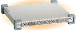
In addition to standard form factors, proprietary switch subassemblies that can be mixed and matched within a larger carrier are available. One example is the VTI Instruments EX71HD High-Density 26.5-GHz Microwave Switch, a 1U-high rack-mountable LXI Class A enclosure that accepts a variety of front-pluggable switch building blocks.
Electromechanical relay topologies include SPDT, SP4T, SP6T, and transfer switches (DPDT), all with 1E6 lifetime and SMA connections. Any combination of up to 12 building blocks can be housed in a single chassis. A typical configuration is shown in Figure 2. A flexible API supports IVI and Linux, exclude lists, relay cycle counting, and storage of up to 128 relay state configurations.
Figure 2. EX71HD Microwave Switch
Courtesy of VTI Instruments
For example, Cytec has the CXM range of multiplexers and matrices with from two to 128 switch points per 19″ rack-mount chassis and a life expectancy of at least 1E6 cycles. Steve Moore, a manager at the company, commented, “We also offer multichassis systems with up to 2,048 switch points. A bandpass of DC to 8 GHz is typical but extends to 40 GHz in some cases. SMA connectors are standard although many other types are available. Control is via GPIB, RS-232, or Ethernet.”
Four versions of the Pickering Interfaces type 60-800 LXI Multiplexer are available with 4, 8, 12, or 16 6×1 multiplexer banks with 20-GHz bandwidth. Terminated versions with up to six six-channel multiplexers and 26.5-GHz bandwidth also are offered. A model with 16 banks of 6×1 multiplex
ers and 40-GHz bandwidth completes the series.
Bob Stasonis, the company’s sales and marketing director, explained, “The variety of choices we give the customer differentiates Pickering Interfaces from our major competitors. We’ve noted that coaxial relay manufacturers continue to improve product life, insertion loss, and isolation. And, isolation is becoming more important as multiple protocols are transmitted on a microwave signal,” he continued. “These protocols need to be isolated from other signals in a switching system to ensure correct communications.”
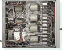
Agilent offers several routes to complex RF switching assemblies. Customers who intend to build their own switching solutions can base them on the L4490A/91A RF Switch Platform, which consists of a 2U-high (90A) or 4U-high (91A) box with a built-in driver and power supply. These LXI-compliant chassis come with software drivers for most common programming environments and 3-D models to support the design and documentation of RF cable layout. Alternatively, a full custom design and construction service is available to produce a switch matrix based on the customer’s exact requirement (Figure 3).
Coutesy of Agilent Technologies
Walt Strickler, the company’s vice-president of business development, switching solutions, explained, “Although most designers are familiar with common SPST, SPDT, and multithrow switches, they may not have encountered the star switch. A four-position star switch can be routed from any position to any other. Without a common, the switch is more balanced: The transmission line lengths are equal and stubs are minimal, resulting in better RF performance.”
EADS North America Test and Services also has long been involved in RF and microwave switching. Charles Greenberg, senior product marketing manager, noted, “As an instrumentation and integration company, EADS North America Test and Services is capable of integrating our standard switching control platforms with switches and other devices, using thelatest available technology to meet industry needs. As an example,” he continued, “we can build a switching matrix to expand a two- or four-port VNA up to N ports for S-parameter measurements of multiport devices. If needed, we can integrate technology to completely calibrate each switch path seamlessly.”In addition, the company provides full custom design and fabrication with cabling, amplifiers, attenuators, directional couplers, and an I/O panel. The systems have a smart software interface that can control switches individually or in groups of user-defined paths. Features include automatic scanning, relay cycle counting, exclude lists to prevent inadvertent unsafe connections, and a predefined power-on state to ensure a safe configuration at startup.
Keithley Instruments offers several RF and microwave switching systems with bandwidths up to 18 GHz. The Model 7116-MWS also provides up to 40 low-frequency channels in the same chassis. The rack-mount system comprises the16-channel 7020-MWS Microwave Switch and the 7001 Switch System Mainframe with a spare card slot.
The five RF relays are connected by semirigid cables to implement the 1×16 multiplexer function but can be reconfigured as five independent 1×4 multiplexers by removing the cables. More than 30 types of cards are available to expand the switching capabilities of the 7116-MWS to include low-frequency, general-purpose, optical, or additional RF up to 2 GHz.
One of the newer high-frequency products from Universal Switching is the Model 10948B DC-18 GHz Four-Channel A/B Transfer Switch System. A transfer switch has a DPDT configuration. In one position, signal A connects to port 1 and signal B to port 2. In the other position, the signals and ports swap. Although a unit that allows individual or ganged control of four transfer switches could be handy in many applications, the datasheet highlights back-up switching in high-reliability communications systems.
Because of its intended use in critical applications, the rack-mount 1U-high 10948B includes redundant power supplies as well as redundant system control interfaces and specially chosen relays to improve reliability. Complete control and status monitoring are possible from the front panel or the dual remote interface. Six models are available with dual RS-232-C,dual RS-422-A, dual RS-485, and Ethernet plus an RS-232-C, RS-422-A, or RS-485 interface.
Summary
Virtually all of the RF and microwave switching modules and systems discussed in this article are based on relays because they have the best overall performance. Wide bandwidth including DC, low loss, and good isolation are especially attractive specifications in a test system. PIN diode and GaAs FET switches cannot offer this combination of features although these technologies have advantages in other types of applications.In spite of the many factors affecting individual relay performance, RF and microwave switching system design doesn’t have to be difficult, but it does need to be thorough. Obviously, the correct type of relay must be chosen to work with specific types of signals. Details such as contact material and relay construction can be avoided by working with well-defined switching modules and components from reputable sources. After all, your job is to develop a test system, not to reinvent the parts used to build one.
References
1. “Relay Contact Life,” Application Note 13C3236, Tyco Electronics, 2000.
2. “Design Guide Microwave Switches and RF Coaxial Relays,” Dow-Key Microwave, 2001.
May 2010
| FOR MORE INFORMATION | Click below | |
| Agilent Technologies | L4490A/91A RF Switch Platform |
Click here |
| Cytec | CXM Series Microwave Coaxial Switching Systems |
Click here |
| Dow-Key Microwave |
14F3S-1/4×4 Reconfigurable Bidirectional Nonblocking Matrix |
Click here |
| EADS North America Test and Services |
Configurable Microwave and Optical Switching Platform 1257 |
Click here |
| Giga-tronics | ASCOR Series 8000 Microwave Switch Systems |
Click here |
| Keithley Instruments | 7116-MWS Microwave Switch | Click here |
| National Instruments | NI PXI-2596 Dual 6×1 Multiplexer | Click here |
| Pickering Interfaces | 60-800 LXI Multiplexer | Click here |
| Universal Switching | 10948B A/B Transfer Switch System | Click here |
| VTI Instruments | EX71HD Microwave Switch | Click here |
