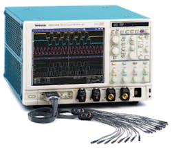
High Performance = ? (Many Factors)
The definition of a high-performance oscilloscope really is all about the customer’s point of view. Two scopes may have the same bandwidth, number of channels, sampling rate, operating modes, and memory length. Yet, one will be bought instead of the other because its software or triggering capability or measurement suite better matches the customer’s application requirements. One scope simply may be much easier to use than another or have a better display.
Of course, there is a minimum specification level that a scope must have just to be in the running. Today, USB-3 and higher-speed versions of several other buses are being designed into new products. To work with 5-Gb/s USB 3.0 signals, scope vendors generally recommend an instrument bandwidth at least 5x the fundamental or greater than 12.5 GHz in this example.
Because digital oscilloscopes sample the incoming waveforms, a high sampling rate must complement wide bandwidth. One way to increase sampling rate is to interleave pairs of channels, and this technique has become popular among all scope manufacturers.
A high-bandwidth scope front end isn’t much use without comprehensive triggering and deep memories. It’s also important to have a range of high-speed probes and accessories so that you aren’t limited to working within a 50-? environment.
When all the supporting and enabling elements are included, the cost of a high-bandwidth scope can be significant. It’s not surprising that customers should want to extract the greatest benefit from such an investment, and one way in which this is accomplished is via application-specific software.
By adding the appropriate software, your new scope can become an automated serial bus compliance tester. Or, it may be more important to provide de-embedding on certain critical serial link measurements. Of course, first the scope must have a level of performance commensurate with the fast bus activity. Then, application-specific software can ensure that the data is acquired and parameters extracted as specified by the relevant standards.
Bandwidth, memory length, sample rate, software, and accessories are some of the more commonly cited factors contributing to a scope’s high-performance classification. But, as Chris Loberg, senior technical marketing manager at Tektronix, commented, “If an engineer is trying to qualify the timing performance of a digital system, it’s important to understand the scope’s jitter noise floor.
Similarly, if the slew rate of a digital circuit is being evaluated, then the scope’s rise-time performance is critical.”
Mr. Loberg mentioned many other specific factors that might be important in certain circumstances, making the point that there is no simple way to rank a scope’s performance that is meaningful to everyone. The effective number of bits (ENOB) value is a concise overall indication of scope fidelity and a meaningful figure of merit. But, although ENOB accounts for many signal integrity imperfections, it does not quantify any one particular type of digitizing system noise or error that may be critical in your application.
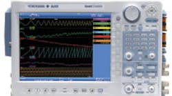
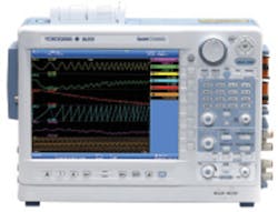
Yokogawa USA’s Joseph Ting, product manager, test and measurement division, agreed that high performance has many facets: “In the lower speed mechatronics and 200-MHz to 1.5-GHz bandwidth midrange, we measure high performance in terms of hardware-accelerated memory handling, waveform and display update rates, and real-time computations. For example, the Model DLM6000’s advanced data stream engine supports up to 2.5 million acquisitions/s. Similarly, the DL850 ScopeCorder GIGAZoom 2 engine allows real-time zooming of up to 10 million times into 2-Gigapoints of real-time acquisition.
“In the ScopeCorder instruments,” he continued, “users need to capture high-speed transients and trend long-term events, often for the same application. The instruments’ dual capture feature addresses both requirements by simultaneously recording at two different sample rates.”
Fidelity
Signal integrity, fidelity, and accuracy relate to how well a signal’s characteristics are preserved along its path through various connections, cables, filters, amplifiers, and ADCs or DACs. Resolution plays a part to the extent that insufficient resolution limits accuracy while high resolution enables but does not guarantee accuracy.
Signal fidelity is one of the major distinctions between digitizers and oscilloscopes. According to Dr. Andrew Dawson, sales and business development manager at DynamicSignals, “Virtually all commercial scopes provide 8 bits of vertical resolution. This usually is sufficient for signal visualization, the main purpose of a scope. Digitizers, however, often have 10, 12, or as many as 16 bits. As a result,” he continued, “digitizer performance historically has been specified by their maximum sampling rate and vertical resolution in contrast to scopes, which more often highlight the input bandwidth.”
Dr. Dawson said that the best measure of a digitizer’s vertical performance is its ENOB. Roughly speaking, the ENOB is the true resolution of the digitizer after accounting for residual noise and distortion. It might be possible to include ENOB as a multiplying factor in a digitizer figure of merit—the higher the better. Nevertheless, such a metric necessarily lumps together parameters that have different importance depending on the application.
ENOB generally is a good thing, but a digitizer with an ENOB of 12 won’t help you if you really must have 10-GHz bandwidth. Similarly, if you need eight channels but only 100-MHz bandwidth, a high ENOB digitizer may be a better choice than two high-bandwidth scopes.
Looked at from a different point of view, some amount of signal degradation is unavoidable in real communications systems, and equipment must be designed to cope with it. The SyntheSys Research BERTscope™ isn’t a scope in the traditional sense but instead combines signal acquisition with jitter injection as well as analysis. The recently released Stressed Live Data option captures and retimes real data to remove timing variations and adds user-specified amounts of stresses including sinusoidal jitter, random jitter, bounded uncorrelated jitter, and sinusoidal interference.
Scope software is available that supports serial data link analysis although it doesn’t provide programmable interference sources. Nevertheless, as with the BERTscope, you can segregate and measure different types of jitter, de-embed signals, and measure bit error rate (BER). The BERTscope Si 25000C, like a conventional oscilloscope, has the bandwidth and sampling precision necessary to capture high-speed signals. In this case, hardware-based pre-emphasis operates to 12.5 Gb/s and hardware-based clock recovery with a built-in equalizer to 28.6 Gb/s.
Bandwidth
Digitizer bandwidth lags that of scopes but continues to improve. Gage Applied Technologies, a DynamicSignals brand, has developed the CobraMax family of high-speed, 8-bit PCI-based digitizers with up to a 4-GS/s sampling rate, 1.5-GHz input bandwidth, and as much as 4 GS of memory. The CobraMax’ ENOB is 7.6 for a 10-MHz signal frequency, diminishing slightly for a 400-MHz signal.
If channel interleaving is used to increase the sampling rate, the delay of one channel’s samples relative to those of the other channel must be precise. In addition, the bandwidths and pulse responses of the two channels including their respective ADCs must be matched to produce accurate results. Nevertheless, traditional time-domain interleaving has become well established and the critical aspects of the associated hardware and software systems perfected.
LeCroy has developed a related digital bandwidth interleave technology (DBI) that increases sampling rate and extends bandwidth. In this approach, a diplexer splits the incoming signal into a band of frequencies totally within the scope circuitry bandwidth and another band of similar width but higher frequency. The higher band is downconverted, amplified and digitized, and finally recombined with the amplified and digitized lower frequency band.
Recombination involves carefully balanced DSP operations that ensure the unwanted frequency-domain images really are rejected and the processed signal accurately represents the original input. The procedure is theoretically sound and has resulted in almost a doubling of bandwidth in high-end LeCroy scopes introduced in the last few years.
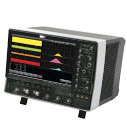
The company’s Kenneth Johnson, senior product marketing manager, explained, “Customers in R&D that use high-performance scopes are developing next-generation products based on the same types of technologies used in scope front ends and ADCs. This is a huge barrier because the two technologies generally have the same bandwidth and the customers want 2x or more bandwidth in their measurement systems to accurately characterize their designs. Initially, we used DBI to double and then triple the bandwidth of our 6-GHz front end, but most recently we released the WaveMaster 8 Zi Series with 30-GHz bandwidth based on an actual 16-GHz front end,” he concluded.
DSP techniques also have been used by several manufacturers to correct channel-to-channel matching and in some scopes to extend bandwidth. In particular, Tektronix has implemented user-selectable bandwidth-extending filters on several models including the latest Model 72004, in this case increasing the typical 16-GHz bandwidth to 20 GHz.
DSP filtering creates a linear phase and precise amplitude vs. frequency gain characteristic as well as an improved rise time. On the other hand, as explained in a Tektronix white paper, a linear phase response makes the Gibbs phenomena associated with a very fast edge more obvious.1
The ringing associated with Gibbs phenomena results from the finite number of harmonics contributing to a square edge and the shape of the amplifier passband. Pre-shoot typically is not seen in a scope without bandwidth enhancement because the rate of phase delay is greater near the 3-dB point than at lower frequencies. Hence, you only observe an overshoot on a very fast edge, some of which is actual and some that is Gibbs related.
Modern DSOs tend to use a relatively flat amplitude vs. frequency characteristic to increase bandwidth. This means that in contrast to older scopes, the 3-dB corner is sharper and the stopband attenuation greater. Typically, rise time is slower and related to bandwidth by a factor of 0.4 or even 0.45 instead of the more traditional 0.35. All of these considerations and alternative technologies address the continuing need for more bandwidth caused by ever faster applications.
Ten years ago, Tektronix announced the use of silicon germanium (SiGe) in the then-new TDS7000 Series Scopes, and IBM’s Dr. Bernie Meyerson expounded the virtues of the semiconductor technology he had helped develop. With this material and IBM’s production know-how, much higher-speed DSOs became possible. Today, scope manufacturers are using their second or third generation of SiGe parts, and further bandwidth gains have once again become elusive as the inherent limitations of SiGe are approached.
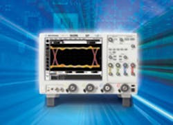
Agilent recently introduced the 90000 X-Series of high-end scopes based on a set of custom ICs built with a proprietary indium phosphide (InP) process. The fastest of these scopes, the 93204A, boasts a native 32-GHz bandwidth. DSP techniques are used to ensure channel matching and calibration, but the InP process is claimed to yield an extremely flat passband response with linear phase. In fact, the channel performance is sufficiently flat and repeatable that the frequency response is specified in the datasheet.
You may never need 32-GHz bandwidth and with a price greater than $250,000 for the 93204A, the customer base is limited. Nevertheless, today these scopes are the fastest direct-sampling DSOs. DSP-based bandwidth enhancement and bandwidth-doubling techniques are not used.
Triggering
Digital oscilloscopes capture signal activity relative to user-defined trigger events where the event can be anything from a simple rising-edge level crossing to a complex sequence of conditions. A large portion of a scope’s capabilities depends on accurate triggering. Conversely, to get the most performance from your high-end scope, you need to understand and make use of its powerful trigger modes.
Cascade triggering in LeCroy’s 8 Zi Series Scopes enhances the selection of 12 SMART triggers with the capability to sequence a combination of three edge and SMART trigger events. The first event arms the trigger circuitry, the second further qualifies the trigger, and the third event determines the data to be acquired. Exclusion triggering is permitted in the Cascade sequence, and the final trigger condition can be linked to a WaveScan™ search.
Many times, the signal of interest is an abnormal one, and with conventional trigger capabilities, it’s up to you to define such a signal well enough that it can be triggered upon. LeCroy’s TriggerScan™ is a rare-event-capture technology based on high-speed hardware that detects undesired behaviors previously defined by a built-in trainer. The signals are captured and displayed in a persistence mode for further analysis.
With TriggerScan, the trigger definition automatically is generated based on possible exceptions to observed normal signals. InfiniiScan Event Identification software performs a similar function for Agilent 90000 Series Scopes.
Agilent, Tektronix, and LeCroy have mixed-signal scopes (MSOs) that combine logic-analysis channels with conventional scope channels. In these instruments, triggering can include the states of several logic channels as well as analog conditions on the conventional channels. This capability, together with limited logic-analysis data capture, is a good solution to modern development projects that mix digital control with analog sensors and actuators, for example.
In the MSO70000 Series MSOs, Tektronix offers the iCapture™ feature that multiplexes any four of the 16 logic signals to be displayed on the conventional scope channels. This means that you can view analog characteristics immediately without having to reprobe digital signals.
Triggering in high-end Tektronix scopes centers around the Pinpoint™ Trigger System, a patented A-B event triggering system that supports complex event setup with very low trigger jitter. In addition, the DSA70000 Series Scopes have a built-in serial pattern trigger operating at rates up to 5 Gb/s to identify user-defined pattern combinations.
Because standard serial buses have well-documented signal behavior, serial bus trigger and decode capabilities are available on many scopes. Agilent makes the distinction that several of its scopes use hardware-based instead of software-based serial bus triggering for the more common buses such as I2C, SPI, RS-232, CAN, LIN, PCI Express (PCIe), and USB. More recently developed or less frequently encountered buses such as SATA, MIPI-D-Phy, and FlexRay use software-based protocol triggering. Some trigger and decode capabilities are limited to scopes with sufficiently high bandwidth.
Probes and Accessories
All high-bandwidth scopes support direct 50-? cable connections, and this is the least expensive way that your measurements can take full advantage of the scope’s bandwidth. Nevertheless, at 20 or 30 GHz, signal transmission is not simple. Conventional SMA connectors are rated as high as 27 GHz, but some may not perform well above 12 or 18 GHz depending on the manufacturer.
Instead, 2.92-mm or type K connectors should be used because of their 40- to 45-GHz frequency response. TCF358 flexible cable is useful to at least 40 GHz but because of its small 3.58-mm outer diameter has almost 2-dB/m loss at 30 GHz. Smaller cables also are suitable but have even more loss and higher cost.
Conventional 10:1 passive voltage divider probes are limited to about 500 MHz and low-impedance or transmission-line 500-W probes to no more than 10 GHz. To probe any signal faster than this or with relatively high source impedance, you need an active probe.
Tektronix Tri-Mode™ Probes provide differential or single-ended connectivity in the same package with bandwidths from 4 GHz to 20 GHz. Agilent’s new InfiniiMax III line of InP-based differential probes with 16-, 20-, 25-, and 30-GHz bandwidth is designed to complement the 90000 X-Series scope bandwidths. And, LeCroy’s WaveLink active differential probes are available with bandwidths from 13 to 25 GHz.
As you might suspect, achieving high bandwidth in an active probe poses a challenge similar to the scope design itself but in a smaller space and with severe power constraints. Typically, the same semiconductor process is used to provide this level of performance, and the cost is high. To compare signals at two different points, you will need to budget between $40,000 and $60,000 to buy two high-bandwidth active probes.
The Tektronix P7520 Tri-Mode 20-GHz Probe lists for $18,600 and Agilent’s N2803A 30-GHz InfiniiMax III Probe for $29,000. LeCroy’s D2505 WaveLink 25-GHz/1.6-Vpk-pk Differential Probe with two Dxx05-SI Solder-In Tips currently costs $19,900.
Input impedance varies greatly with frequency in a conventional 10:1 passive probe because of the large capacitances involved and at full bandwidth is only a few hundred ohms. Transmission-line probes vary less but have only 500-? (10:1) or 1,000-? (20:1) input impedance at DC. High-bandwidth active probes typically have DC resistance of 100 k?, such as the Tektronix Tri-Mode Probes, or less. LeCroy’s D2505 specifies >120-? AC resistance over the full bandwidth.
Agilent Technologies’ Dave Cipriani, R&D manager, oscilloscope business, commented, “Probing is a key area for us because it’s the entire measurement system that delivers measurement accuracy. Our job isn’t done unless we enable our customers to debug efficiently and have confidence that their designs meet key standards via our software compliance packages. Attention to the total high-speed measurement system is how we distinguish our high-performance scopes.”
Software
Software can be grouped into a few categories in addition to signal integrity. One of these is compliance testing where software specific to a certain protocol sets up channel parameters, timing, and trigger conditions; acquires the data; and analyzes it according to the specification.
Tektronix has developed the TekExpress software platform for compliance testing with support for three groups of standards: SAS/SATA, 10Gbase-T Ethernet, and USB 3.0. Agilent offers a wide range of compliance test software for USB 2.0, DDR1/DDR2/DDR3, Ethernet 10/100/1000Base-T systems, MIPI, and HDMI. LeCroy’s QualiPHY software handles compliance testing for DDR2, PCIe, SAS2, and SATA among others. A range of compliance test fixtures complements the software modules.
Another popular type of software deals with the physical effects of serial data links, offering such facilities as equalization, pre-emphasis, and de-embedding. Pre-emphasis or de-emphasis, depending on your point of view, accentuates data bits after transitions by reducing the amplitude of the other bits or by increasing the transition bits. Either way, the effect is to reduce the eye-diagram degradation caused by limited media bandwidth. It is a form of transmission equalization.
At the receiver, closed eyes can be opened by suitable filtering, which serves to reverse the frequency-dependent attenuation of the medium. Several kinds of equalization are used. LeCroy’s Eye Doctor is software that can de-embed the effects of cabling and test fixtures, model pre- and de-emphasis, and emulate equalization schemes. Similar functionality is provided by Agilent’s Serial Data Equalization software and Tektronix’ Serial Data Link Analysis software. For many scopes, the capability to import and run MATLAB scripts affords even greater flexibility.
LeCroy offers specially configured scopes as serial data analyzers. Obviously, the hardware must have sufficient bandwidth, sampling rate, and memory length to acquire large amounts of fast serial bus data. Beyond that, the software adds tools for jitter measurement, eye diagram analysis, de-embedding, BER displays, and time interval analysis. Similarly, the company has developed disk drive analyzers, also based on high-end scopes.
Summary
Although software enables a large part of a scope’s usefulness, the hardware first must be capable of addressing your application. This is the reason so much emphasis is placed on bandwidth, sampling rate, and memory length.
If the necessary signals are accurately acquired, any number of parameters can be extracted by the appropriate software tools. Some of these tools are built in such as the FFT and a suite of waveform measurements. Others, including jitter and compliance testing, usually are optional.
Processing power and architecture vary greatly among scopes so the best way to evaluate one is with your actual application. Especially for measurements that involve statistics or complex events, long memories are essential. But beware: All that data has to be manipulated several times as measurement algorithms operate on it. If you need to work with long memories, develop some representative test suites with multichannel acquisition, math operations, and maybe a long FFT. Now see how quickly competing scope models execute the test sequence and display the results.
Scopes are very complex instruments. Whether or not you consider one to have high performance depends on a large number of factors including control panel responsiveness and personal preference. The continuing innovation and increases in all the usual metrics of bandwidth, sampling rate, and memory length are impressive and support the advancement of a wide range of engineering disciplines. Nevertheless, high performance is defined by how well a scope addresses all aspects of your application, and only you can determine that.
| FOR MORE INFORMATION | Click below | |
| Agilent Technologies | 90000 X-Series Scopes |
Click here |
| GaGe, a DynamicSignals Brand |
CobraMax Digitizer |
Click here |
| LeCroy | WaveMaster 8 Zi Scopes |
Click here |
| SyntheSys Research |
BERTscope Si 25000C |
Click here |
| Tektronix | MSO72004 Mixed-Signal Scope |
Click here |
| Yokogawa Corp. of America |
DL850 ScopeCorder |
Click here |
Reference
1. Pickerd, J. J., DSP in High-Performance Oscilloscopes, Tektronix, 2005.
