Newer standards are particularly well suited to certain types of test applications. For example, because LXI does not restrict module form factor, large switching matrices are much more easily constructed in this format than in a smaller PXI chassis. Similarly, AXIe features six times the area and power of a standard 3U PXI module so it is inherently better adapted to housing high-power, complex circuitry.
Nevertheless, enhancements continue to be made to the PXI standard and new modules introduced. The PXI Systems Alliance (PXISA) website lists many of the alliance member companies and the types of modules they provide.1 The National Instruments (NI) website has similar information in a list of PXI third-party products.2 A PXI module classification chart based on these two sources is shown below.
Predictably, many new modules improve upon older instrument specifications by being more accurate, lower cost, higher speed, or lower noise. However, innovation is not a zero-sum game: At the same time that the performance of existing types of products is being upgraded, different kinds of PXI modules also are appearing.
This process goes on all the time but has accelerated in recent years. A look at a November 2000 issue of the VXI and PXI Newsletter showed the early emphasis was on 6U products to compete with VXI.3 Of course, the larger 6U size also was necessary for many functions because circuit miniaturization and integration were a long way from today’s levels. During 2000, GenRad introduced a 6U mainframe chassis, and Geotest-Marvin Test Systems launched the 6U 100-MHz GX5150 Digital I/O Tester.
A 2007 PXI, Test & Technology Resource Guide included the views of the PXISA President Loofie Gutterman on the first 10 years of PXI as well as a series of interviews with industry leaders organized as an article by Bob Stasonis.4 Mr. Stasonis had written a similar story in 1999, and the contrasts between the two are important.
In 2007, Geotest’s Senior Product Marketing Manager Mike Dewey said, “The 1999 article…on the future of PXI standards alluded to the emergence of 6U PXI. As we know now, the adoption of 6U has never matched that of the 3U form factor.” He went on to say that Geotest had been successful partly because the 6U format existed, and in addition, both Geotest and GenRad had been more comfortable initially in adopting PXI because of the option to use either 6U or 3U.
However, as Mr. Stasonis cautioned, the articles contain a wide range of opinions. Steve Krebs, director of engineering at KineticSystems, forecast 6U growth in his 2007 interview. “The next five years will see additional requirements and growth in 6U PXI. As single-platform system requirements increase, the 6U PXI form factor will be the vehicle to construct such systems.”
On the same topic, David Owen, business development manager at Pickering Interfaces, added, “6U PXI has apparently failed to establish dominance in the larger test market…. PXI will need to look at new applications going forward to see if the added real estate will help it address higher I/O count and asynchronous testing requirements.”
In 2007, the PXI Express (PXIe) enhancement was relatively new as is the multicomputing (PXImc) extension today. Both changes emphasize speed. In 2007, Mr. Gutterman stated, “The introduction of PXIe enhanced the already high-performance PXI bus bandwidth and opened the doors to a multitude of high-bandwidth applications that cannot be supported by any other platform…. [And] we have maintained full backwards compatibility with PXI, allowing for hybrid PXI and PXIe systems.”
In comments made for this article, Tim Carey, product manager for PXI systems at Aeroflex, said, “By decoupling signal processing and RF subsystems, the Aeroflex PXI 3000 Series can leverage…rapid advances in processing power at any stage during the life of the equipment. Low test times are the result of very fast responding hardware and the performance gains derived from the use of multicore processors,” he continued. “Multiple simultaneous measurements and multidevice (DUT) and multistandard testing become a reality when realizing the benefits of multicore processing through the inherent open software architecture.”
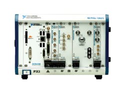
Figure 1. Phase Matrix RF/MW Modules With NI Controller
The general availability of PXI RF subsystems, such as the 3000 Series, is only a relatively recent occurrence. When PXI was introduced in 1997, most companies thought RF instruments could not be built in the 3U form factor. In 2002, NI introduced the 2.7-GHz four-slot 3U PXI-5660 RF Signal Analyzer. In an April, 2005 EE-Evaluation Engineering article, Ascor’s Bill Nicklin described a 4.9- to 6-GHz 3U PXI downconverter.5 Today, a 6-GHz capability often is quoted for new 3U PXI modules, Aeroflex’s 3060 Series RF Combiner being a good example.
The RF/microwave (RF/MW) PXI modules launched by Phase Matrix in 2009 extended measurement system capabilities to 26.5 GHz. Figure 1 shows a typical combination of NI and Phase Matrix modules. Also in 2009, NI introduced the PXIe-5663E 6.6-GHz Vector Signal Analyzer (VSA) and PXIe-5673E 6.6-GHz Vector Signal Generator (VSG). More recently, NI launched the PXIe-5665 3.6-GHz RF VSA, and Agilent released the M9392A VSA with a frequency range from 50 MHz to 26.5 GHz.
Diverse Module Capabilities
Chances are you can address your test application through PXI. There are enough available chassis, signal conditioners, analog and digital I/O modules, oscilloscopes and digitizers, switches, and RF equipment that most of your needs can be met. It’s necessary for a critical mass of basic module types to exist before a large number of special-purpose modules are introduced, and this has occurred for PXI.
In some cases, a hybrid system is the best solution for a test application. The particular instrument you need may not be available as a PXI module or is much more economical in a different format. For example, a large LXI switch matrix might be used in conjunction with a PXI test system.
RF
In general, however, the need for a hybrid approach is being reduced because of the great variety of recently introduced PXI modules. According to Michael Granieri, vice president for advanced programs and business development at Phase Matrix, “Although there was an industry movement in hybrid systems a few years back, most of our customers today are making the transition to PXI from other form factors. In many cases, our customers are demanding RF/MW functionality in PXI that previously was available in VXI and our rack-mount instruments,” he explained. “The small size, low cost, speed, and modularity afforded by PXI as well as the emergence of synthetic instrument technology are fueling this renaissance in small form-factor instrumentation.”
A radar pulse measurement highlights some of the recently developed Agilent RF/MW PXI capabilities. “The bandwidth of wideband chirped radar bursts typically exceeds [that] of traditional vector signal analyzers,” said Steve Narciso, R&D section manager at the company. “Combining the MP9362A-D01 Downconverter and the M9202A 2-GS/s 12-bit Digitizer modular instruments with the 89600 VSA software…provides customers with a familiar…analysis package. The high-speed PCI Express bus used by the digitizers offers impressive test speeds compared to other options.”
Figure 2. 3U Model 3065A RF Combiner
Courtesy of Aeroflex
Also related to RF test, Aeroflex’s Mr. Carey described how PXI improved throughput and test coverage for smart phones, “Modern chips used in mobile phones have vendor-specific test modes to help accelerate various aspects of test…. This requires the test equipment to…track the state of the DUT and make measurements at precise intervals in synch with the device. Doing so eliminates a large overhead associated with sending individual commands to both the DUT and tester for each test state.
“….Smart phones have multiple radio access technologies and a variety of RF test interfaces. Where the test item permits, it is possible to execute measurement of some radio technologies in parallel, for example WLAN testing in parallel with cellular testing. This can save time, but requires more RF instrumentation. …The flexibility of PXI makes this easier to implement than with boxed instruments,” he concluded. Figure 2 shows the Model 3065A RF Combiner typically used in this type of testing.
Digital
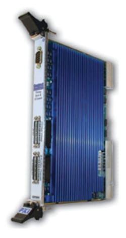
Geotest’s Mr. Dewey discussed PXI products the company recently launched: “The biggest area of advancement for us is in higher performance digital products such as the 6U GX5961 Digital Subsystem [shown in Figure 3] that include timing generators with 1-ns edge placement, per-pin PMUs, and per-pin programmable drive/sense levels. All of these features are new to PXI and now rival features that historically have been associated with proprietary ATE architectures and to some extent with older VXI products.
Figure 3. 6U GX5961 Timing and Sync I/O Board
Courtesy of Geotest-Marvin Test Systems
“Another area…is the development of PXI FPGA modules, which support easy customization by the user both with hardware and firmware,” he explained. “The GX3500 with its self-contained expansion board allows customers to easily build custom PXI instruments, and the availability of free web-based FPGA tools provides customers with a cost-effective development environment.”
The company’s GX3500 is a user-configurable FPGA 3U card with 160 digital I/O. The FPGA has access to all of the PXI bus, clocks, and triggers so you can create a custom PXI instrument using this card. An expansion board can be included in the module to provide buffered I/O for TTL, differential TTL, LVDS, and ECL. In addition, a video generator board for VGA, PAL, and NTSC interfaces is available.
To obtain all the benefits associated with PXIe, greater demands were placed on clock and trigger precision. The NI PXIe-6674T Timing and Multichassis Synchronization Module was described by Matthew Friedman, senior product manager for automated test at NI:
“The module generates and routes clocks and triggers between devices in a PXIe chassis. In addition, it can route these signals to other PXI and PXIe chassis as well as third-party instrumentation. The module unlocks the advanced LVDS trigger buses, PXIe-Dstar A, B, C on PXIe, while fully supporting the PXI trigger bus. It can generate a highly stable 10-MHz clock based on an on-board precision OCXO reference and a second clock up to 1 GHz from the DDS clock generation circuit.”
A cPCI module shares exactly the same J1 connections to the PCI bus as are used on PXI modules. However, cPCI modules lack the J2 connector. This means that cPCI modules cannot receive or send trigger or clock signals on the J2 bus but otherwise are compatible with PXI.
Modules have been developed to address several kinds of automotive and avionics bus protocols. For example, Goepel electronic makes PXI controllers for FlexRay, LIN, and MOST automotive buses. Data Device Corporation provides cPCI modules for MIL-STD-1553 avionics buses. Because measuring instruments such as DMMs and oscilloscopes also are available in PXI, a complete test system can be built in one form factor.
Analog
Special analog functions, such as linear variable differential transformer (LVDT)-to-digital conversion, are available in the PXI format. The cPCI-75LD1 from North Atlantic Industries has four or eight LVDT measurement channels based on two-wire or three- and four-wire digital converters. A three- or four-wire connection provides a derived reference and is insensitive to temperature effects, phase shift, and oscillator instability, making it the preferred mode of operation. This module has 16-bit resolution with 0.025% full-scale accuracy and inputs that autorange from 2.0 to 28 Vrms.
Charles Greenberg, senior product marketing manager at EADS North America Test and Services, described the Racal Instruments 3U PXI 3164x-4 Arbitrary Waveform Generator (Arb), “Although the 3U PXI package has limited space, we have developed a four-channel, 14-bit, 125-MS/s Arb. It has two 500-kword pages of waveform memory per channel, and while one page is playing its waveform, the other page can be refreshed in a glitch-free ping-pong architecture. In addition, the channels can be used in a master-slave mode as well as an advanced sequenced mode.”
A unique capability of the 3164x is temporary fault injection. You can choose to replace part of the current waveform during a sync pulse cycle with a different segment of waveform. This feature is particularly useful when simulating random and intermittent errors. In addition, the Arb is available in a two-channel model.
Also emphasizing analog performance, Pickering Interfaces has developed the Model 41-660/661 3U PXI Programmable High-Voltage Attenuator. Each of five differential channels in the -661 or 10 single-ended channels in the -660 accepts input voltages as high as 600 V and attenuates them by selectable factors from 10x to 160x, finally sending the buffered signal to a 50-? output. The input impedance is 1 M? for the -660 and 0.666-M? differential and 0.500-M? common-mode for the -661. Both modules have 20-kHz bandwidth and a typical 13-V/µs slew rate.
Chassis
Of course, there are limitations associated with the 3U form factor. For example, Agilent’s Mr. Narciso described an automotive test application the company developed for a customer. “DUT power and DUT-specific loads were provided outside the PXI chassis,” he said. “The 30-W per PXI module limit was simply not sufficient so an external 1U rack-and-stack quad power supply was used along with a PXI module that controlled 30-A relays in a custom chassis that also contained high-current, DUT-specific loads and a special cooling system for them.”
As part of Agilent’s entry into the PXI market, the company developed the M9018A PXIe Chassis with 16 hybrid slots. This means that you can plug any new PXIe module or a hybrid-compatible PXI module into any slot. Unless the local bus J2 signals have been used in an application, only a simple connector swap is required to make most legacy PXI modules compatible with a hybrid slot.
The new chassis provides per-slot cooling up to 42 watts. That’s still not sufficient for the automotive application Mr. Narciso described, but is a good example of the higher power chassis available. In this case, the total available power is listed as 859 W when operating from 220 to 240 VAC. The maximum supplied power is reduced to 649 W when the chassis is operated on 100 to 120 VAC.
In an April 2010 EE-Evaluation Engineering article, Pickering’s David Owen described the company’s Model 41-752 Battery Emulator, which requires the high-power 40-923 chassis that provides up to 700 W.6 For this and the Agilent chassis, temperature derating applies although it’s expressed in different ways.
Both chassis are 4U high and draw cooling air in from the bottom, exhausting it out the back. Obviously, you cannot achieve adequate cooling if the bottom of the chassis is restricted. Agilent says to leave a 1U space to achieve the claimed cooling performance; Pickering does not give specific application advice. The Pickering chassis has four fans where Agilent uses three. In either case, you probably would need to test a high-power configuration under actual operating conditions before knowing with certainty the chassis capabilities at 55°C.
Conclusion
If you’re not already building your test systems in the PXI format, maybe you should be. According to the PXISA, more than 1,500 modules exist to solve analog, digital, instrumentation, and RF/MW requirements. On the other hand, PXI is not a universal answer. Large switching matrices, high-power assemblies, and metrology-grade instruments may never be available in PXI.
Mr. Owen summed up the situation: “Different platforms have certain fortes, be it cost, synchronization, power, size, or familiarity, and all major test and measurement platforms are designed to work together from a software standpoint. In the past, our switching fed RF/MW signals to rack-mount instrumentation. Today, these instruments are just as easily located in the same PXI chassis as our switching modules. [Nevertheless, for many applications,] hybrid systems are going to be an important part of future test systems as they have been in the past.”
References
1. http://www.pxisa.org/Products.html
2. http://www.ni.com/pxi/third_party_links.htm
3. VXI and PXI Newsletter, Vol. 12, Issue 1, November 2000, http://www.teradyne.com/atd/resource/docs/ai7/VXI_newsletter.pdf
4. Gutterman, L., “PXI: Happy Birthday to a Mainstream Platform,” PXI, Test & Technology, Volume 7, Number 2, Summer 2007, p. 7, http://www.pxionline.com/emag/PXI%20Smr07%20w-security.FULL.pdf
5. Nicklin, B., “Extending the Frequency Range of RF/Microwave Measurements,” EE-Evaluation Engineering, April 2005, pp. 56-59.
6. Owen, D., and Stasonis, B., “A Solution for Testing Battery Management Systems,” EE-Evaluation Engineering, April 2010, pp. 20-24.
| FOR MORE INFORMATION | Click below | |
| Aeroflex | 3060 Series | Click here |
| Agilent Technologies | M9392A 26.5-GHz VSA | Click here |
| Data Device Corporation | MIL-STD-1553 Bus Module | Click here |
| EADS North America Test & Services | 3164x-2/4 Arb | Click here |
| Geotest-Marvin Test Systems | GX3500 FPGA Module | Click here |
| Goepel electronic | Bus Controllers | Click here |
| KineticSystems | Relay Multiplexer | Click here |
| National Instruments | PXIe-6674T Timing Module | Click here |
| North Atlantic Industries | cPCI-75LD1 LVDT Converter | Click here |
| Phase Matrix | 26.5-GHz RF/MW Modules | Click here |
| Pickering Interfaces | Model 41-752 Module | Click here |


