There is an expectation from consumers that today’s electronic products will just work and that electronic manufacturers have continued to improve the quality of their products. In most cases, this has been achieved by employing inspection systems to monitor and identify any problems within the manufactured product. This information is used to fix the product and fine-tune the manufacturing process that may have caused the problem in the first place.
Any inspection system, whether electrical- or image-based, needs to detect as many defects as possible. A major challenge in this process is determining if the inspection system has accurately detected a defect. Test procedures that run on the inspection systems need guaranteed high defect-detection capability without any increase in the number of false failures.
False failures can be very expensive in labor and repair costs as well as the material replacement and the potential reduction in long-term product reliability. False failures also can lead to issues with the process control systems as they try to correct process issues, which really are inspection-system issues.
Inspection systems need to be 100% reliable in real defect detection, and there are many tools that can be used to identify test program quality, provide and measure stability, and generate lists of potential defects that can and cannot be detected.
There mainly are two types of electrical test systems used in PCB inspection. Final test normally is performed by a functional test system or integrated system test, which has access by edge connectors or external connectors and tests the complete board or functional blocks on the board. The second type of electrical tester breaks the board up into functional blocks and individual devices using in-circuit test techniques to isolate each device or block. Traditional in-circuit test systems or manufacturing defect analyzers use a bed-of-nails interface while flying-probes systems have four or more movable probes that perform simple electrical measurements.
Defect Types
Before we look at test quality, it is important to understand the types of defects we are trying to find. For diagnostic purposes, defects can be divided into two types.
The first type is a defect such as a short, open, missing, or nonfunctioning device that stops the PCB from working correctly. These normally are easy to verify by a diagnostic and repair technician because they are absolute defects that affect the performance of the board. If the test system cannot detect this type of defect, then it is straightforward to understand why.
The classic example of an electrical test system not finding a clear defect is a missing capacitor when it is used for decoupling power on the board. One capacitor missing from a large number of parallel devices cannot be measured because it is well within the tolerance of the total capacitance used to decouple the board.
The second type of defect is a subjective defect, which may or may not cause a PCB to work correctly or cause a failure in the future. These are defects whose measurement by the test system is close to the limits of the test of a particular device. With electrical test, these limits normally are the tolerance limits from the device manufacturer but actually should be the limits required for the PCB design to work correctly.
Another example of a subjective electrical defect is the capacitance measurement from a test technique like FrameScan or TestJet/VTEP (for testing open pins on connectors or devices) that is learned using a known-good board. In electrical test, these subjective measurements can be moved to quality absolute limits using signal measurement algorithms to eliminate the effects of noise. These tools improve measurement reliability and reduce the false failure possibilities associated with subjective defects.
This is in contrast to image inspection systems where the number of subjective measurements generates a high degree of false failures and false passes. Component position, solder-joint shape, and color are simple examples of defects that can be classed as subjective and generate the significant number of false failures common with imaging systems.
Automatic Test Program Generation
Generating test programs by hand should only be performed by experienced engineers who are trying to test critical functions of a PCB. For general electrical inspection, an automatic test generation method should be used so that the source design information generates the tests. CAD information, including parts lists with component types and tolerances, interconnection, and layout information can be critical in determining possible defects such as adjacent-pin and track shorts.
With PCB information, tests can be generated to match the board’s configuration. Simple tests like shorts can be automatically generated which reflect the nets used on the board and take into account any low-resistance paths. These low-resistance paths then can be measured to make sure the impedance path is correct for each board.
All the nodes in the net list must be tested for shorts and opens. If for some reason they are not tested, such as lack of electrical access, that fact can be documented. Similarly, all the devices that are listed in the parts list should have tests generated for them or a reason given as to why not. The list of devices that cannot be tested can be reviewed, and other test techniques can be applied to add test coverage.
If a digital device is highlighted as not tested because it has no test vector-based model, then either a test can be created or a capacitive open test technique such as FrameScan can be used to verify that each pin of the device is connected to the correct net. Other devices that cannot be tested can be passed to other inspection systems. For example, imaging techniques can be used to inspect decoupling capacitors.
After the test program has been completed, there is confidence that the PCB can be tested to a certain level. However, test coverage still is theoretical and needs to be verified by using the program to test the target PCB.
Test Program Verification and Calibration Tools
Once the test program has been debugged using the target PCB and fixture, then a complete review of the test-program quality can take place. Some of this will be a manual process, but many tools are available to help review test coverage and test quality.
The stability of any test can be verified by running the test multiple times and making sure the test always passes. If the test can be run at least 100 times without failing, it still may have problems, and statistical analysis then can be applied to analyze the accuracy and stability of the test.
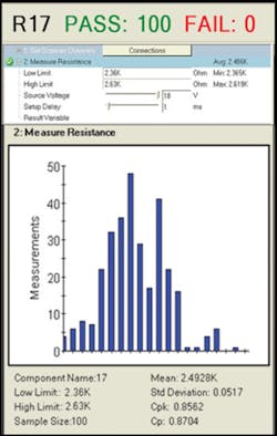
Figure 1 presents the results from a simple test of a resistor that has been run 100 times. The analysis shows that the average measurement is 2.48k with a mean of 2.49k, demonstrating that the measurements are not central. The standard deviation (sigma) shows how much variation exists from the mean. A small standard deviation indicates that the measurement results tend to be very close to the mean whereas high standard deviation indicates that the results are spread out over a large range of values.
The Process Capability (Cp) number is a simple and straightforward indicator of process capability based on the calculated sigma number; the Process Capability Index (Cpk) is an adjustment of Cp for the effect of noncentered distribution. In this example, the six-sigma measurement limits for this test would be 2.345k and 2.655k. This is around 6% tolerance rather than the current 5% tolerance that has been calculated by the automatic test generator based on the component tolerance and the effects of the surrounding circuits and fixture.
Therefore, this test statistically may fail about one to two times in every 100 tests. A Cpk above 2 would be optimal for this type of measurement because this would indicate just one failure in 50 million—but any Cpk number above 1 probably is acceptable. As Cpk deals with asymmetric issues where the average measurement is closer to one of the two limits, it is the preferred indictor of a stable measurement.
All analog tests need to be reviewed to get the highest Cpk possible with either the tests being adjusted to tighten the measurement value or the limits adjusted to match the board design limits. If it is impossible to improve the Cpk number for a particular test, then it needs to be highlighted as a possible source of false failures and reviewed if it fails during the production test.
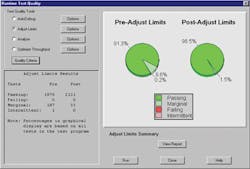
Due to the number of tests for analog devices on a board, a test system should be able to take inputs from the programmer, automatically make changes to the test to help stabilize it, and give confidence that tests will find defects and not produce false failures. Figure 2 shows the results before and after adjustments with only 33 tests out of 2,164 considered marginal and in need of additional manual debug to avoid possible future false failures.
The automatic test generator deals with shorts test generation, and the statistical analysis provides stable analog measurements. However, the problem is more complex because a major source of defects on a board is digital device pins. Typical defect opportunities for an analog device with two pins would be three while digital devices have multiple pins. As defect opportunities are a function of pin-count, then a 16-pin device has 17 opportunities while a processor can have 1,500+ opportunities.
Failure rates measured as defects-per-million opportunities (DPMO) for devices are around 250 while the equivalent pin faults are around 400. This means that a board with 300 analog components and 10 digital devices, with an average of 64 pins per device, would have similar DPMO rates between the analog and digital. The digital-pin DPMO for this example would be around 0.25 defects per board, making it important to verify that all defects on pins of a digital device can be detected.
To detect defects on digital inputs and outputs with test vectors, all outputs need to go high and low during a test, and the test system needs to simulate that each input stuck low and then stuck high will cause the digital test to fail. If the test system drives the input low for the entire test and the test passes, then it indicates that an input stuck low defect or an open pin that floats low cannot be detected.
The same is true for a simulated high and the open pin floating high case. In some cases, it may be difficult to generate vectors that can test all inputs. When that occurs, additional test techniques can be used, such as analog open techniques to give incremental coverage on input or output pins.
If tests cannot be added at this stage, then other test stages can be informed of the deficiency and tests can be developed if required. The escaped defects, identified this way, can be used as a relevant starting point for any diagnostic when tests fail at later stages.
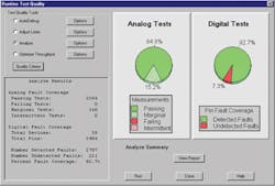
Once the analog and digital quality tools have been run on the debugged PCB, then a report can be generated that summarizes the results as in Figure 3 with detailed information about each defect available. This can be used to verify the defect coverage for production or as part of an acceptance document for test procedures provided by third parties, such as a test programming house.
Electrical Inspection in Production
Once volume production is available, then additional quality tools can be used to gather more information about the quality of the test procedures. For the first few boards produced on the manufacturing line, all analog values can be collected for every test, and the same statistical analysis can be performed to make sure that the Cpk values are still within requirements (Figure 4).
Any intermittent digital tests also can be addressed at that time, but typically digital tests will be stable if normal in-circuit programming procedures are used such as applying inhibits and disables to all surrounding devices. Digital test quality tends not to change over time unlike analog tests where device tolerances do vary from batch to batch and supplier to supplier.
During production, only failure information normally would be recorded but, due to the potential drift in values, occasionally full value logging should be turned on to check that the test program still is stable and that device tolerances have not changed. Fixture interfaces also may deteriorate with additional contact resistance on certain nodes that can affect guarded analog tests, and changes in the Cpk number will help identify problems.
A third reason for turning on full datalogging and comparing against previous versions is to make sure the test program has not been changed without it being documented. Documented changes will occur with ECOs to the product and changes to the manufacturing process. However, by comparing results, undocumented changes can be found and corrected, giving the manufacturer confidence that the test program, fixture, and test system are performing as they did when the test procedure was introduced.
Conclusion
Using source information taken from the CAD system to generate tests automatically will provide a one-to-one relation between the PCB and the test program that has been generated by the test system. Using statistical tools on the analog measurement with Cpk values greater than one (six sigma) provides confidence in the accuracy and stability of the test procedure and minimizes and identifies potential false failures.
Automated digital hardware fault-insertion techniques support accurate defect detection and escape information, which also can be used at functional and system test to aid with diagnostics. Production audits of the test procedure will keep the program stable and identify any changes that have been made, resulting in test procedures with the highest defect-detection capability and the lowest false failure rate.
About the Author
Michael J. Smith has more than 30 years experience in the automatic test and inspection equipment industry with Marconi, GenRad, and Teradyne. He has authored numerous papers and articles and chaired iNEMI’s Test and Inspection Roadmaping Group for a number years. Smith received a BSc(Hons) in control engineering from Leicester University and is a Member of the Institution of Engineering and Technology. [email protected]


