Enabling Simulation and Test of Custom OFDM Signals
Orthogonal frequency division multiplexing (OFDM) has become attractive for many current and emerging commercial applications because it provides a combination of data throughput, scalability, and robustness. Orthogonal frequency division multiple access (OFDMA) is a multi-user variant of OFDM where subcarriers can be allocated among multiple users of the channel.
Two potential applications for OFDM and OFDMA are software-defined radio (SDR) and cognitive radio.1 Using OFDM and OFDMA for these applications provides advantages similar to the benefits for commercial applications; however, their inherent complexity poses some unique challenges. The flexibility of the modulation formats, baseband coding, and subcarrier allocation requires complex baseband functionality in the SDR or cognitive radio.
OFDM parameters may potentially be customized for more secure wireless data transmission. However, OFDM customization can introduce additional complexity for both system design and hardware testing.
Creating and Analyzing OFDM Signals
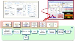
One of the early steps in a design flow for a custom OFDM SDR application is to create and analyze the custom or proprietary signals in simulation to design the radio. While this can be time-consuming in itself, these tasks can be simplified by using flexible OFDM models in simulation and signal analysis software (Figure 1).
Figure 1. SystemVue Design Environment with Flexible OFDM Models
The system design environment provides flexible OFDM models for quickly constructing the necessary signals. Within this environment, the engineer can configure parameters to customize the preamble, data payloads, pilots, and the number of subcarriers. A graphical user interface simplifies this process by allowing the engineer to enter parameter data to configure the OFDM signal. The resulting signals then can be evaluated and modified in simulation to ensure functionality for the SDR or cognitive radio application.
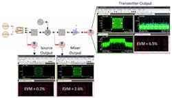
Once the custom OFDM signal is created in simulation, the SDR transmitter can be designed. Impairments for the SDR transmitter design can include LO phase noise, filtering, and power amplifier gain/phase compression/distortion. Vector signal analysis (VSA) software can be used in simulation to evaluate error vector magnitude (EVM) and signal distortion at various stages along the modeled transmitter design, as shown in Figure 2. This enables the system engineer to quickly gain visibility into the SDR’s design performance and evaluate sources of signal distortion to perform system-level design trade-offs.
Figure 2. Simulated RF Transmitter Design with a Custom OFDM 64 QAM Signal
Figure 2 shows a simulated RF transmitter design with a custom OFDM 64 QAM signal. The IF signal is generated using a flexible OFDM source with customized OFDM parameters, filtered and upconverted to RF using a mixer and LO with modeled phase noise, then amplified with a power amplifier (PA) which has modeled gain compression characteristics. VSA simulation measurements are performed at various stages along the modeled transmitter design, including the custom OFDM source output, the mixer output, and the PA output.
The EVM at the output of the custom OFDM source is 0.2%. The EVM is 2.6% at the output of the mixer and 6.5% at the output of the PA, showing the signal distortion occurring along the transmitter design from the modeled design impairments.
Combining Simulation and Test
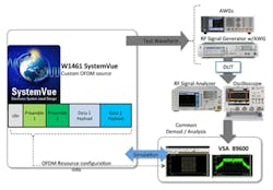
Once custom OFDM signals have been created in simulation and analyzed with signal analysis software for SDR design, design simulation and test equipment can be combined to create real-world custom OFDM signals on the test bench for DUT testing, as shown in Figure 3. Note that the custom OFDM signal can be an ideal signal modeled in simulation, or it could include modeled impairments such as RF design impairments or multipath fading.
Figure 3. Design Simulation and Test Equipment Combined to Create Real-World Custom OFDM Signals
The custom OFDM signals created in the design simulation environment are downloaded to a wideband arbitrary waveform generator (AWG), which turns the simulated IQ data into real-world IQ signals that are fed into the external IQ inputs on an RF signal generator. Alternatively, the custom signals could be downloaded directly into an RF signal generator with an internal AWG. The RF signal generator modulates the IQ signals and upconverts to RF frequencies for use during testing.
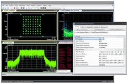
After the signal has passed through the DUT, the custom OFDM signal can be analyzed with the same VSA software previously used in simulation. Instead of running in simulation, it now runs with an RF signal analyzer, a digitizer, or digital oscilloscope. Figure 4 shows a custom OFDM measurement result achieved by combining simulation and test.
Figure 4. Custom OFDM Measurement Performed by Combining Simulation and Test
Conclusion
Customizing OFDM signals may be attractive for emerging SDR and cognitive radio applications with similar data throughput, scalability, spectral efficiency, and robustness benefits as for commercial applications. Customized OFDM signals also may be attractive for secure wireless data transmission.
Using design simulation and signal analysis software, OFDM signals can be created and analyzed in simulation for SDR system design. VSA software can be used in simulation to evaluate SDR design performance and verify the functionality of the custom OFDM signal. Simulation and test equipment then can be combined to create and analyze custom OFDM signals on the test bench.
The same VSA software used in simulation also is used with test equipment to demodulate custom OFDM signals to evaluate hardware performance. Using these solutions, engineers can streamline their development flow and help reduce system integration risk when designing, analyzing, and testing custom OFDM signals for SDR and cognitive radio applications.
Reference
1. Jue, G. and Cutler, B., Agilent Cognitive Radio Algorithm Development and Testing, Agilent Technologies, White Paper, August 2009.
About the Author
Greg Jue is an applications development engineer/scientist working on aerospace/defense applications at Agilent Technologies. He pioneered combining design and test solutions at Agilent; wrote the design simulation section in Agilent’s new LTE book; and authored numerous articles, presentations, and application notes. Before joining Agilent in 1995, Jue worked on system design for the Deep Space Network at the Jet Propulsion Laboratory, Caltech University.


