Pulse Radar System Testing with an LXI VNA
Radar is a remote sensing technique used to detect, locate, and analyze objects by emitting electromagnetic waves, more specifically microwaves, and measuring the time interval between the transmission and reception of the corresponding scatter or echo of the waves back from the object. A pulsed radar system transmits short bursts or pulse signals instead of continuous-wave (CW) signals. In a pulsed radar system, a microwave pulse is transmitted and its corresponding echo is received before the next pulse is sent. In doing so, the time interval between sending and receiving the signal can be accurately measured and, consequently, the distance to the object determined.
Pulse radar systems require power amplifier modules to deliver high peak power that cannot be driven by CW signals without destroying the radar system. The performance of radar components, such as power amplifier modules, can be determined using a vector network analyzer (VNA) and a new technique called pulse profile mode to perform scattering (S-parameter) measurements.
S-Parameter Measurements with Pulse Profile Mode
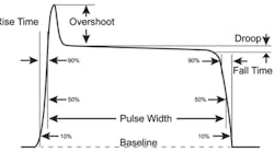
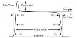
To analyze the time-dependent behavior of a device during a burst, a VNA performs a pulse-profile measurement. Typical parameters required to characterize the time-dependent behavior include rise time, overshoot, and droop. A representative pulse waveform is shown in Figure 1. For this measurement, the VNA must have time resolution significantly higher than the pulse duration. A typical VNA’s time resolution ranges from 3 µs to 20 µs for measurements in the frequency or time domain, which is not fine enough to analyze behavior vs. time with sufficient resolution. Most VNAs have a measurement bandwidth of 600 kHz or less, which is the limiting factor for high time resolution of pulse widths of 1 µs or less.
Figure 1. Pulse Waveform with Various Characteristics Identified
A new technique developed at Rohde & Schwarz employs wideband detection and fast data recording to greatly improve pulse profile measurements. Pulse profile analysis of pulsed signals or S-parameters with pulsed stimulus is limited by the sampling rate of the A/D converter, the processing time between two data points, and the available bandwidth. The sampling rate and the time required for data processing between two points limit the time resolution while the measurement bandwidth determines the minimum rise and fall time of the pulse that can be analyzed.
The bandwidth-limiting factors in the analyzer are the analog bandwidth of the receivers and the capabilities of the digital signal processors (DSPs) for digital filtering. A high-end VNA such as Rohde & Schwarz’s LXI-compliant ZVA has an analog bandwidth of 15 MHz (with some performance degradation to 30 MHz), but the IF filters of the DSPs offer adequate performance only for normal CW or time sweeps with a 5-MHz bandwidth.
The receivers of the ZVA down-convert the sampled data to the IF frequency at a sampling rate of 80 MHz, which results in a time resolution of 12.5 ns. In addition to the sampling time, there is the data processing time between two measurement points, which is a bottleneck for achieving high-resolution measurements in the time domain.
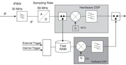
However, pulse profile measurement resolution can be dramatically improved by sampling the raw data and storing it directly without filtering. Instead of using hardware, the DSP software on the ZVA is used to perform digital down-conversion and digital filtering after recording. The A/D converter continuously digitizes the data with a sampling rate of 80 MHz and writes it into high-speed RAM, which ensures that no delay occurs between the samples of individual measurement points, as shown in Figure 2.
Figure 2. Fast Data Recording Using the Improved High-Performance Pulse Profile Technique
Because of the high sampling rate, a measurement point is created every 12.5 ns, which is the time resolution. The trigger signal, usually derived from the rising edge of the pulse, determines the zero point in time. Consequently, the exact time relation between trigger detection and the incoming RF pulse also can be measured. This relation is especially important for determining the correct trigger delay in point-in-pulse measurements vs. frequency or level.
The ZVA performs extremely fast pulsed measurements, and with more than 10 sweeps per second at 1,001 test points, devices can easily be adjusted during the pulse profile measurement. In addition to periodic single-pulsed signals, this new technique handles double pulses as well as user-defined pulse trains. Devices stimulated using pulses with frequency and amplitude modulation, such as chirps, also can be analyzed.
The new techniques also benefit measurement of the S-parameters of devices with group delays in the order of the pulse width, which has been difficult or even impossible until now. The stimulated RF signal may no longer be present at the device’s input by the time the VNA receives the transmitted RF signal from the output. Before calculating the S-parameters, the VNA mathematically shifts the wave quantities by the device’s group delay. A specific time delay can be assigned to each wave quantity depending on the measurement direction so the VNA correctly displays the gain (S21) vs. the entire pulse duration.
Data Transfer Simultaneous with Sweep
Since the ZVA is LXI conformant and therefore LAN enabled, trace data can be transferred via the Gigabit Ethernet at the same time measured data is being captured by the high-speed buffer RAMs and calculated by the DSP software. As such, data transfer time from the ZVA to a PC for analysis is insignificant in the case of repeated measurement sequences. High throughput is important if any tuning or adjustments have to be made for the DUTs, such as power amplifier modules.
General Test Configuration
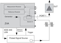
Another advantage of LXI’s LAN connectivity is apparent in applications for which the device under test requires a pulse-modulated input signal and either a signal generator with pulse modulation or a vector signal generator providing complex waveforms can be connected to the VNA via LAN. The modulated RF signal of the generator is directly input into the generator path of the VNA instead of using the nonmodulated internal VNA (Figure 3).
Figure 3. Test Signal Generator Set Up as a Modulated Signal Source
Because the modulated signal also is measured by the reference receiver when it passes through the internal coupler, system error correction can be applied to S-parameter measurements. A system error or level calibration recorded under CW conditions also applies under pulsed conditions and need not be repeated when the duty cycle is changed.
As the VNA controls the power and frequency of the external generator via LAN, this setup is suitable for pulsed measurements vs. frequency and level where the ZVA varies the signal generator settings for different frequencies and different power levels. This allows the characterization of the DUT without the need to control the signal generator from an external PC.
LXI Browser Interface
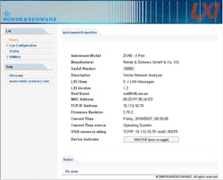
Web servers are integrated in all LXI devices permitting interface and instrument settings to be made via a W3C-compliant browser simply by typing the instrument’s host name or IP address in the address field of the browser. Figure 4 shows the ZVA’s LXI welcome page that enables fast configuration and setup and provides the status information of the instrument as well as a log of all internal and external LXI events, for example, the LXI event messages exchanged by the VNA and pulsed signal source in Figure 3.
Figure 4. LXI Web Interface of VNA
Summary
S-parameter measurements using a VNA with the pulse profile mode provide an accurate interpretation of component performance such as that of power amplifier modules in pulse radar systems. Rohde & Schwarz’s LXI-compliant ZVA VNA supports the bandwidth and high sampling rate needed to perform extremely fast pulse profile measurements. Since the ZVA is LAN enabled, it simplifies interconnecting devices and instrument setup and makes data transfer time to the PC negligible.
Acknowledgement
This article is adapted from Testing S-Parameters on Pulsed Radar Power Amplifier Modules, an application note by Roland Minihold, Rohde & Schwarz, 2009.
About the Author
Jochen Wolle is chairman of the LXI Conformance Committee and represents Rohde & Schwarz on the Board of Directors of the IVI Foundation and LXI Consortium. He is director for R&D test and measurement at Rohde & Schwarz Asia Pte Ltd and studied electrical engineering at the Technical Universities of Darmstadt and Munich.
