Accurately measuring very low-level signals requires more than just good instrumentation. Special care is needed throughout the measurement system because the very small size of low-level signals exposes error sources that usually can be ignored with larger signals.
Differential circuitry often is used with low-level signals because it minimizes noise pick-up problems. Ideally, external noise will couple equally to both sides of a differential signal and can be removed by a circuit’s common-mode rejection. To ensure equal coupling, the two conductors needed for each differential signal must be identically routed on a PCB. Twisted-pair wiring is used between assemblies. Differential circuitry also avoids the single-ended signal corruption caused when imperfect PCB layouts allow ground current mixing.
All low-level signals are subject to thermally induced voltage offsets based on the Seebeck effect. A junction of dissimilar metals, such as found in reed relays, produces a small voltage when a temperature gradient exists along the length of the conductors. The connection between the nickel-iron relay blade and the associated copper lead wire forms a thermocouple, but the junction itself isn’t the problem. The Seebeck effect states that any conductor generates a voltage when a temperature difference exists along its length. When two different kinds of conductors are joined, the voltages generated by each don’t cancel as they could were only one type of metal used.
Nevertheless, compared to electromechanical relays with exposed contacts, reed relays have many advantages. The contacts are hermetically enclosed in a sealed glass tube so no external contamination can affect them. On the other hand, the 50:50 nickel-iron alloy often used for the reed blades isn’t a good conductor and typically is plated in the contact area. According to a Pickering Electronics technical paper, “Commonly used materials are ruthenium, rhodium, and iridium…. Tungsten is often used for high power or high voltage reed switches due to its high melting point.”1 The type of plating and size of the contacts govern the quality of the reed switch.
Reed relays
VTI Instruments’ Tom Sarfi, vice president of Product Management and Support, said, “…the biggest challenge we see with low-level switching is when an end user is interested not only in switching low-level signals, but also high levels as well with the same relay. Customers often think that if a relay is capable of switching 20 amps, it should also be capable of switching milliamps. The relays that are best suited for high-level switching are electromechanical, and these relays typically are specified with path resistances when switching a measureable load. Consistent contacts are made only when switching some level of load [because] this ensures that arcing occurs to remove any oxidation that may have been formed on the contacts. “
Sarfi emphasized the benefit of hermetically sealed switches that avoid this problem. He said, “We have designed two different switch modules (one used on the eCASS Navy program) that use hermetically sealed relays that are designed for high- and low-level switching. Hermetically sealed relays prevent oxidation from occurring on the contacts, and therefore the higher load is not required to ensure low path resistance when switched.”
When reed relays are used in higher current applications up to about 2 A, self-heating can be a problem. In reference 1, the author touched on many interrelated factors when discussing carry current—the current that the reed relay can support through its contacts without long-term damage. “The carry current is determined primarily by the contact resistance of the relay and the heat sinking to the environment. As the current increases, the temperature of the reed blades increases until it reaches a temperature where the material is no longer ferromagnetic (Curie temperature). Once that temperature is reached, the relay contacts may open since the blades no longer respond to the magnetic field.
“The blade temperature is clearly dependent upon the current and relay path resistance. The normal assumption is that this is a square law (with current) relationship. In reality, the temperature rise is significantly more than a square law since the metallic resistance also increases with temperature, the magnetic field drops with temperature because of the coil resistance rise, and the mechanical properties of the blade can change. Consequently, like all relays, exceeding the rating can result in a kind of thermal runaway.”1
For very low-level signals, reaching the Curie temperature is not a concern, but thermal offset voltages still can be generated by heating within the relay structure. Minimizing the power dissipated in the relay coil is one way to reduce this effect. Power = I2 x R, so power and the associated temperature rise can be minimized by maximizing the coil resistance.
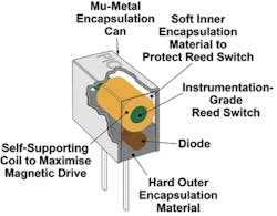
For comparison purposes, a general-purpose Littlefuse type HE3600 500-mA, 200-VDC reed relay has a nominal 5-VDC coil voltage and draws about 10 mA. This means that the coil resistance is approximately 500 Ω. In contrast, the resistance of some Pickering Electronics Series 100 5-V relay coils is 3,300 Ω. In terms of power, the Littlefuse relay dissipates 25/500 = 50 mW vs. 25/3,300 = 7.6 mW for the Pickering relay. Figure 1 shows construction details for a typical Pickering “soft center” reed relay.
Courtesy of Pickering Electronics
A relay’s symmetrical construction also can mitigate the generation of thermal offsets. If both blades and connecting wires experience the same but opposite thermal gradients, the effects will cancel. A relay can be made with two identical Form A switches in the same coil so it can be used differentially to reduce thermal offsets. The differential connection ensures that thermal offsets will closely match each other even though self-heating causes unequal temperatures across the package. Of course, a differential relay is needed to handle many low-level signals that also are differential.
Regardless of a reed relay’s design, some amount of thermal error voltage still will be generated. A National Instruments technical paper discussed several approaches to eliminating this error. The basic idea is to measure a relay’s contact resistance when a small test current is passed through the closed contacts. Because the relay is actuated, self-heating will develop a thermal offset voltage. The voltage measured across the relay contacts will include that voltage. A second measurement made with the current source off will only measure the thermally generated voltage in series with the closed contacts. Subtracting the second measurement from the first allows the relay contact resistance to be accurately calculated.2
This approach is technically sound but must be used with some care. Time also is a factor because a greater temperature differential is created when the coil is energized for a long time than when it is driven by a short pulse. So, to obtain the greatest accuracy from the two-measurement method, you need to drive the coil in the same way that the relay will be used in your application. In addition, because the relay’s environment affects heatsinking, the relay’s mounting should be representative of how it actually will be used. You also need to provide power to any nearby external sources of heat.
Product examples
Thermal effects
Multiplexers specified as having Nx2 channels are intended to be used with differential signals. Some of these products also list a x1 configuration, typically with twice as many channels as for the differential x2 connection. An example is the National Instruments NI PXI-2503 24-channel relay multiplexer/matrix. This product uses electromechanical relays and quotes a differential thermal offset <2 µV for the x2 configuration. The single-ended x1 thermal offset is not quoted.
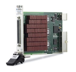
The higher density NI PXI-2530B reed-relay-based switch module provides 128 single-ended channels or 64 two-wire channels (Figure 2). The typical x1 thermal offset voltage is quoted as <50 µV. The differential thermal offset is not given. Neither the PXI-2503 nor the PXI-2530B is specifically recommended for very low-level signal switching, although either easily handles general-purpose signal switching. The reason for comparing them is to highlight the very large difference that may exist between single-ended and differential thermal offsets. You need to understand which specification applies to your application and what level of thermally induced voltage can be accommodated without significantly affecting measurement accuracy.
Courtesy of National Instruments
Keysight Technologies’ Dave Tenney, product manager, GP instruments, discussed the various switching selections compatible with the company’s 34970A/34972A data acquisition/switch unit. The Models 34901A and 34902A both are two-wire multiplexers with a built-in cold junction reference for use with thermocouples. The 34901A is based on electromechanical relays, supports up to 1-A loads, and quotes thermal offset <3 µV. The 34902A uses reed relays and has a maximum current of 50 mA and thermal offset <6 µV. The advantage of the reed relay version is 250-ch/s switching speed vs. only 60 ch/s for the 34901A with electromechanical relays.
Because a low-level switch manufacturer has control of both the actual switching element and the surrounding electrical and thermal environment, very low thermal offsets can be guaranteed even for single-ended switches. For example, Pickering Interfaces’ Shaun Fuller, switching product manager, referred to the Model 40-525A switch matrix that claims <5 µV single-ended thermal offset, achieved through careful design techniques. He also mentioned the 40-620 23-channel PXI multiplexer with a differential thermal offset specification of <1 µV. On the other hand, suboptimal signal connections and cabling that the user provides from the source to the switching product’s terminals can significantly degrade overall performance.
Enhancements and trade-offs
High-density assemblies necessarily place relays close to each other. Without magnetic shielding, the magnetic field from the coil of one reed relay can affect the pull-in/drop-out actuation of adjacent relays. This effect can be minimized by using relays with integral mu-metal shielding.
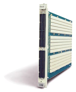
Crosstalk from a large signal on one relay to a small signal on another is a function of relay proximity as well as wiring layout and impedances. For the Astronics Test Systems Model 1260-43HS VXI switch matrix, crosstalk within any one of the three 8×24 single-wire matrices is specified <-70 dB at 100 kHz, <-55 dB at 1 MHz. Thermal EMF is listed as <10 µV.
In general, crosstalk (dB) = 20 log10 (voltage ratio). So, 70 dB = a voltage ratio of 3,162:1, or a 1-V, 100-kHz signal on one channel can produce a voltage of 316 µV on another. It’s clear that even if the crosstalk specification were -100 dB rather than -70 dB, you can’t mix volt-level signals and microvolt-level signals. Depending on how the matrix signals are routed to the module’s front-panel connectors, it might be possible to reduce crosstalk for the 1260-43HS by routing all larger signals to one of the three physically separate matrices and small signals to one of the other two—for example, just use the upper and lower sections (Figure 3).
Courtesy of Astronics Test Systems
For applications that need a much higher level of isolation, Universal Switching’s Series 70000 and RS70000 coaxial relay assemblies are available in configurations from 1×2 up to 1×24. Both series use a machined aluminum housing to mount the BNC signal connectors and as part of the channel-to-channel shielding. Greatly reducing the relay density and providing continuously shielded signal paths yield typical isolation as high as 160 dB at DC, 140 dB at 10 MHz, and 120 dB at 100 MHz.
In contrast to crosstalk, which is a measure of the isolation between signal paths, passive intermodulation (PIM) distortion is proportional to signal path nonlinearity. PIM is caused by nonlinearities in the signal path that allow mixing products to form when two or more carrier frequencies are present. The cable itself, relay contacts, and connectors can all contribute to a system’s PIM.
Dow-Key Microwave has developed a range of special low-PIM coaxial switches that is guaranteed to exhibit <-160-dBc PIM at 1,870 MHz when tested with +43-dBm carriers at 1,930 MHz and 1,990 MHz—a typical test requirement. In comparison, a standard switch’s PIM might be 30 dB higher.
Leakage is another switch-related issue that’s especially important when dealing with high-impedance signal sources. Charles Greenberg, senior product marketing manager at Astronics Test Systems, explained that the company developed a low-level parametric test system that supports two- and four-wire measurements of devices up to 4,000 pins. “The systems can measure low-level resistance, capacitance, inductance, and leakage without damaging low-voltage structures on a device,” he said. “Reed relay switches were selected for their low leakage and capability to operate over millions of operations. Low-leakage cables to the test head were an important part of achieving system performance.”
Cytec’s CEO Nick Turner said that the company often bases designs on low-leakage reed relays, adding that, “Getting down below 500 femtoamps leakage is almost an art. It requires a lot of prep and hand assembly work. Circuit board material tends to charge and discharge so a lot of the signal wiring is done above the circuit board material. The boards have to be cleaned well, baked to remove any moisture, and then handled with gloves to avoid contamination. Relays, connectors, wire, and shielding are all picked based on isolation specifications. And then there still is a certain amount of settling time involved before you can take accurate readings. The only way around settling time,” he concluded, “is to use a driven guard circuit which greatly speeds up the measurements but adds another layer of expense since everything has to be wired to maintain the guard circuit.”
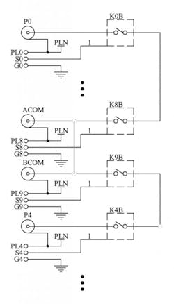
Figure 4 is a simplified schematic of a multipurpose module Cytec often provides for low-level applications. It can be used with high-isolation BNC or SHV connectors to achieve <1-pA leakage and with triax connectors when both a driven guard and grounded noise shield are needed. Supported configurations include dual 1×4, 1×8, and 2×4.
Courtesy of Cytec
Application examples
As Figure 3 shows, in spite of VXI being very much a legacy technology, its size continues to make it an attractive format for large switching applications. LXI has proven to be a good alternative in some situations. Pickering’s Fuller described an application that involved replacing a customer’s existing VXI-based low-thermal EMF switch matrix because of slow switching speed and obsolescence concerns.
Fuller said, “LXI was chosen as the most suitable solution due to its large form factor. Constructing a matrix of this size (56×33) would both be clumsy and have restricted performance if implemented using small form factor modules such as PXI. Connecting multiple modules together would require complex cabling, and besides the obvious cost/size penalties, the interconnection process would lead to the generation of unacceptable thermal EMFs—an important parameter for this requirement. In addition, test program generation using multiple modules would be more complex when compared to programming a single entity.”
Electromechanical relays were used in this 2U-high, 19-inch rack-mount solution because the customer’s application also involved higher voltages. The design is available as a standard product, and there also is a reed-relay version that features faster operating speed.
Universal Switching’s Norton Alderson, vice president of marketing at the company, described an application recently addressed for a client that operated a survivability and vulnerability lab. “This facility contracted us to automate the connectivity and distribution of a large number of vibration sensors, thermocouples, accelerometers, and strain gages. The requirement initially called for 160 of these various sensors to be connected to a nonblocking full fan-out switching system and specified that the system must be capable of expanding to at least 256 inputs. The inputs needed to be differential to help eliminate noise and ground loops since all the sensors were physically located in, on, and around the UUT in another room.”
Alderson continued, “The output of the unit was to initially connect to 192 individual channels of various test equipment such as numerous data recorders, oscilloscopes, and analyzers. The test equipment was single-ended coaxial type and located near the switching system. In addition to being able to connect a given sensor to multiple destinations (analyzer, recorder, etc.) at the same time, a few additional requirements were that the unit must be able to verify a signal path with nonintrusive signal injection, accept ±10V DC coupled signals, and have >80 dB of crosstalk isolation (DC – 100 kHz), <0.1 dB of gain accuracy, >200-k Ω input impedance (differential), SMB signal connectors, and a 10/100 LXI Ethernet control port.”
He concluded, “We provided a solution based on our modular System S2562E that can be configured as small as a 32×32 and as large as a 256×256 in only 5RU of rack space. In addition to this switch box, we also included our input buffer chassis and our output buffer chassis for a total of 15RU.”
Also discussing a multichannel system, Cytec’s Turner described a challenging resistance-measurement job. He said, “…the customer wanted to measure insulation resistance between any two points on a device with 128 pins. The specification that made it difficult was the need to measure resistance in the range of 50 T Ω [1 T Ω = 1,000,000,000,000 Ω]. While this wouldn’t be too bad for a small system such as an 8×2, it becomes increasingly difficult as you make the system bigger because all of the relays are in parallel and the resistance across open relays and to ground divides as the system scales up. Luckily, we have switch modules that can measure leakage down into the femtoamp range so the system worked well even as a 128×2 matrix.”
Turner concluded, “The bigger issue… is related to all the complexities associated with these types of measurements such as environmental conditions, charge times, and grounds. Systems like this are extremely sensitive to anything going on around them that can contribute negatively to the measurement.”
Evolution
Rare-earth-plated reed relays have been the standard solution to low-level switching applications for many years. However, solid-state switching continues to make inroads. Pickering Interfaces’ Model 40-680 PXI solid-state multiplexer features virtually unlimited service life, a low thermal offset <2 µV, no bounce when changing states, and typically 1-nA off-state leakage current. However, because it is a FET-based design, each of the 160 channels is limited to 20-mA continuous current and has an on-state resistance between 150 Ω and 350 Ω . Various configurations are possible from a single 160-to-1 multiplexer to a 20-bank 8-to-1 multiplexer.
References
- Mallett, K., “The mystery of reed relays: Understanding specifications,” Solid State Technology, October 2014.
- Removing Thermal Offset Errors from Contact, Switch, and Relay Resistance Measurements Tutorial, National Instruments, White Paper, October 2014.
For More Information


