Interfacing high-speed, high-power DUT signals
As designers deal more with high-power and high-speed signals, interconnect and DUT interfacing become increasingly important parts of a test setup. Vendors have recently introduced probes, fixtures, adapters, cables and cable assembles, and interposer solutions to serve high voltage and power, high-speed digital, and RF/microwave applications. And some have focused on mass-interconnect systems, including one with optical connectors that don’t degrade over many mating cycles.
High voltage and power
Courtesy of Teledyne LeCroy
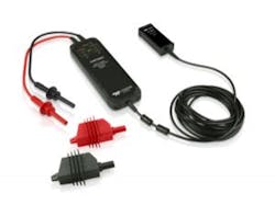
Ken Johnson, director of marketing and product architect, and Jeff Krauss, applications engineer, both at Teledyne LeCroy, described the HVD3605 high-voltage differential probe (Figure 1) introduced in July as an addition to the company’s HVD differential probe series. The HVD3605 probes, they said, “have a safety rating of 6,000 Vrms common-mode while maintaining an exceptional common-mode rejection ratio. The differential voltage range with this probe expands up to 8,000 Vpk before saturation when capturing short-duration overshoots.” They added that the low-frequency gain accuracy remains 1%. “These probes are ideal for measuring 4,160-V three-phase signals given their high common-mode safety rating and wide differential voltage rating,” they added.
Also in July, the company introduced the HVD3206, a safety-rated 2,000-V (DC + peak AC) and 1,500 VDC probe per the IEC/EN 61010-031:2015 standard. This probe was specifically designed to address solar PV string inverter requirements for 1,500 VDC inputs. The company said this higher DC input voltage will become common in utility-scale string inverters since it allows economies of scale (more PV modules on each string) and lower installed cost. The HVD3206 has the same 1% gain accuracy and 2,000-V peak differential voltage range, 120 MHz of bandwidth, and CMRR performance as the 1-kV safety-rated HVD3106 probe.
Also introduced were “no accessory” (-NOACC) versions of the existing HVD3102 and HVD3106 probes. The HVD3102-NOACC and HVD3106-NOACC offer an alternative to customers seeking a 1-kV safety-rated, high-voltage differential probe but not requiring the full range of tip accessories. All HVD3000 Series probes connect to the oscilloscope through the ProBus interface. The ProBus interface provides power and communications to the probe so there is no need for a separate power supply or batteries, and attenuation is automatically selected based on the oscilloscope gain range (V/div) setting.
Teledyne LeCroy also offers current probes that do not require the breaking of a circuit or the insertion of a shunt to make accurate and reliable current measurements. Based on a combination of Hall effect and transformer technology, Teledyne LeCroy current probes are suitable for making accurate AC, DC, and impulse current measurements. Current ranges from a maximum of 30 A to 500 A; frequency ranges from maximums of 2 MHz to 100 MHz.
Keysight Technologies addresses power electronics test with its B1505A power-device analyzer/curve tracer and B1506A power device analyzer for circuit design, as described in an August special report.1 Alan Wadsworth, market development manager for semiconductor test, said adapters are available for these instruments to allow high-power test fixtures to be used with inTest Thermostream forced-air systems. “This eliminates the need to place the devices in the thermal chamber and run long cables to the DUT, which can be a source of oscillation issues,” he said.
For its part, Tektronix offers current probes and high-voltage probes such as the TPP0850 standard passive probe with a 2,500-V range, 800-MHz bandwidth, and 1.8-pF loading. “Accurate and repeatable measurements require high-quality probes,” said Scott Davidson, product marketing manager for oscilloscopes. “Tektronix provides power supply designers the best measurement accuracy with high-voltage single-ended (ground-referenced) probes.” In addition, he said, Tektronix supplies high-bandwidth and high-sensitivity current clamp probes rated for use on bare wires.
And for use with the Tektronix PA1000 power analyzer, the company has a breakout box. “The Tektronix breakout box provides a safe and easy way to make wiring connections between your DUT and the Tektronix power analyzer,” said Seshank Malap, applications engineer for power analyzers. “Your device power cord plugs directly into the outlet on the breakout box. Connection to the power analyzer then is simple, using the input lead set with 4-mm safety banana connectors provided as a standard accessory with the power analyzer. The breakout box is especially useful for applications like low standby power measurements where it is important to connect the current shunt toward the load side. A special connection configuration on the breakout box makes accurate standby power testing a breeze.”
And finally for high-voltage test, Keithley, a Tektronix company, offers the configurable Model 8020 high power interface panel (discussed in our August report1) and the Model 8010 high power device test fixture. The latter provides safe and easy connections for testing packaged high power devices at up to 3,000 V or 100 A. It supports connections for a high-voltage SourceMeter SMU instrument (Model 2657A), one or two high-current SourceMeter SMU instruments (Model 2651A), and three low-power SourceMeter SMU instruments (other Series 2600B or Model 4200-SCS SMU instruments).
High-speed digital
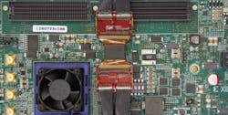
For high-speed digital test, in July Keysight introduced a ball grid array (BGA) interposer solution for testing DDR4 x16 DRAM designs with a logic analyzer (Figure 2). Using the Keysight W4636A DDR4 x16 BGA interposer solution, engineers can quickly and accurately capture address and command signals and a subset of data signals for debugging designs and performing functional validation measurements for data rates up to 2,400 Mb/s.
Courtesy of Keysight Technologies
The company reports that the Keysight W4636A is the world’s smallest DDR4 x16 BGA interposer solution for use with a logic analyzer, making it suitable for testing designs with tight space restrictions.
The company notes that as the memory industry transitions to DDR4 designs, engineers working on next-generation memory systems face significant challenges. Probing and accurate signal capture are becoming increasingly critical for debug and validation of new designs. The W4636A DDR4 x16 two-wing, small-KOV (keep-out volume) BGA interposer—the latest addition to the W4630A Series DDR4 BGA interposer family—is for engineers who need to view DDR4 x16 DRAM traffic and have limited KOV on their systems under test. It also is for engineers who need to perform functional compliance tests on DDR4 devices with ADD/CMD signals.
The W4636A interposer solution provides direct access to most of the signals on a JEDEC-standard DDR4 x16 96-ball DRAM with low loading and minimal impact to signal integrity on embedded-system designs. The interposer solution is designed to be used with the Keysight U4154B logic analysis system, E5847A ZIF (zero insertion force) probes, and U4201A cables for functional compliance and performance validation and analysis on ADD/CMD and a subset of DQ (data).
“Our customers need a selection of DDR4 BGA interposers to cover a variety of system designs,” said David Cipriani, vice president and general manager of Keysight’s Oscilloscope and Protocol Division, in a press release. “With the W4636A interposer and U4154B logic analyzer system, engineers with tight space restrictions are ready to test DDR4 x16 DRAM in their systems.”
For engineers who require access to all ADD/CMD/DQ/DQS at data rates more than 2,400 Mb/s, the W4633A x4/x8 DDR4 BGA interposer and W4631A x16 DDR4 BGA interposers capture all ADD/CMD/DQ/DQS signals at data rates of at least 3.2 Gb/s.
The U4154B logic analysis module with 4-Gb/s state speed enables engineers to trigger on specific events and capture DDR4 traffic. When used with the new DDR4 interposer solutions, B4621B DDR decoder and B4622B compliance software toolset, this module provides functional test capability for system integration in the memory industry with visibility of the upper data byte lane up to 2,400 Mb/s.
RF/microwave
For RF/microwave measurement applications, several companies are continuing to offer interconnect products described in our previous look at the topic.2 For example, Times Microwave offers its SilverLine bench-use test cables in unarmored configurations. MegaPhase also has test cables, including the BT Series 75-Ω test cables for benchtop testing of CATV, video, IPTV, and broadcast products. And Mini-Circuits supplies its CBL-NM-75+ series 75-Ω precision test cables, which feature rugged yet flexible cable construction for easy bending and connections in tight spaces.
GORE offers its PHASEFLEX microwave/RF test assemblies, which, the company said, provide excellent phase and amplitude stability with flexure. The assemblies operate to 110 GHz and employ an internally ruggedized construction that ensures measurement repeatability while the cables withstand demanding conditions such as continuous flexing, temperature cycling over broad temperature ranges, and frequent connecting and disconnecting to the instrument or device under test.
Courtesy of Pasternack
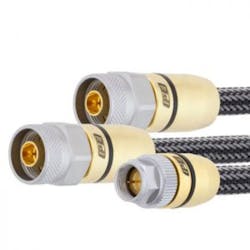
Pasternack, a manufacturer and supplier of RF, microwave, and millimeter-wave products, announced in March the release of its newest line of 75-Ω test cables with operation up to 3 GHz (Figure 3). The company said these rugged cable assemblies are designed to withstand the rigors of test lab use and applications in 75-Ω communications systems. The connectors are threaded to ensure an accurate and secure connection to both the DUT and the analyzer. The test cables are suitable for engineering labs, production environments, and quality testing facilities and for use with 75-Ω S-parameter test systems. Insertion loss is <0.5 dB at 3 GHz, and typical return loss is 28 dB. The assemblies include an armored jacket that meets ANSI/SCTE 99 2009 pull force and ANSI/SCTE 98 2009 tightening torque standards and are capable of 100,000 bends minimum.
These test cables are primarily designed for technicians working with cable TV, MoCA 2.0 and MoCA 1.1 (Media over Coax Alliance), and DOCSIS (Data over Cable Service Interface Specifications). To meet your own unique needs, you can use Pasternack’s Cable Assembly Designer web application, which allows you to design and customize RF cable assemblies based on 1,300 connector types and 115 different coaxial cables (including Twinax).
Mass interconnect
For mass interconnect applications, in June Virginia Panel Corp. introduced the i2 MX connector, which, the company said, builds on the success of the popular i2 Micro iCon, offering a configurable connector in the same 0.8-inch footprint. Combined with its slimmer, metal engagement knob and its oblong cable exit, the i2 MX provides maximum cable bundle clearance and improved stackability.
The i2 MX also boasts a removable, all-metal back shell to gain access to complete troubleshooting and maintenance procedures. The back shell and cable exit are designed with EMI shielding to minimize interference and protect signal integrity. VPC said it has engineered the i2 MX for more than 10,000 mating cycles.
And MAC Panel introduced its X-BEAM optical connectors in February and has published a case study involving a customer who tests high-volume, high-performance automotive products.3 The customer needs to connect up to 16 multimode cables to its ATE systems.
The customer had used standard commercial optical cables and connectors, but this approach could require at least 30 minutes per fixture to set up, including connector cleaning and maintenance. Further, the connector performance degraded after multiple mating cycles. By employing the X-BEAM connectors, which provide a minimum of 2,000 mating cycles (5,000 typical) with no cleaning or maintenance, the customer was able to achieve setup times of less than 30 seconds.
References
1. Nelson, R., “Pursuing efficiency from wafer to system,”
EE-Evaluation Engineering, August 2015, p. 16.
2. Nelson, R., “Cables, connectors augment test applications,”
EE-Evaluation Engineering, March 2015, p. 24.
3. X-BEAM Performance Optical Connectors, Case Study,
MAC Panel, 2015.
For more information


