The consumer drone market has seen a sharp surge in sales in recent years due to the popularity of small commercial drones. With their speed and agility, as well as their ability to capture amazing in-flight videos and photos, the demand is understandable—drones are cool.1
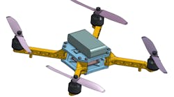
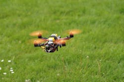
Many consumers purchase ready-to-fly models from brands like DJI and Parrot, but that’s not the only option. There is a large community of users who are taking the DIY (do-it-yourself) route and building their own (Figure 1).
Designing a drone 100% from scratch can certainly be a challenge, requiring the user to have expert knowledge about control systems, aerodynamics, materials, payload, fabrication, and electronics to ensure that the drone will have a stable pattern of flight and reliable maneuverability.2 As a reader of EE-Evaluation Engineering, you undoubtedly have knowledge in one or more of these areas, but you are unlikely to have expertise in all.
On the job, you would probably assemble a team of electrical, mechanical, aerodynamics, and manufacturing engineers to complete such a project. But if you want to experiment on your own, there are many free and low-cost tools out there that can aid you through the entire design-to-flight process. We’ll discuss them below.
Computer-aided design (CAD)—designing the drone
If you decide to build the frame from scratch, you’ll first need to consider the size, shape, and placement of all components including the motors, electronic speed controls (ESCs), propellers, batteries, battery compartment, wiring, and connectors.
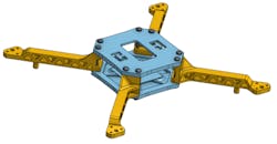
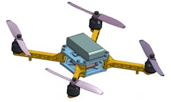
A great way to visualize the design is to model it using CAD software. Within a virtual environment, you can continuously modify the design until it’s exactly how you want it (figures 2 and 3).
Some low-cost CAD options include Onshape, a fully cloud-based CAD system that has a free tier for open source and public design projects and Autodesk Fusion 360, another cloud-based tool with a free one-year startup license available for hobbyists, enthusiasts, and makers.
Computer-aided engineering (CAE)—optimizing the design
Engineering simulation, a tool for optimizing and validating designs, allows for the CAD model to be tested in a virtual environment. Perhaps you are considering two different arm designs for the drone; rather than building two different versions of the drone, you can use finite element analysis software to predict the von Mises stresses (Figure 4) and maximum displacements (Figure 5) in the arm under the calculated lift force.
Now compare the two designs:
- Design 2 has a hollow circular cross section with holes along the length with a weight of 6.32 grams (ABS plastic) compared to a weight of 8.56 grams for Design 1.
- Design 2 has no stress concentration points; it has a very uniform stress distribution. Design 1 has a small region of high stress where the arm is thinned.
- Design 1 has maximum displacement of 0.41 mm at the tip vs 0.37 mm for Design 2.
Then comes the tough part, sticking the landing (Figure 6).
Note: The scale factor for the deformations in Figure 6 has been increased for better visualization.
One of the biggest benefits of simulation is that it allows you, the designer, to quickly optimize your designs in a virtual environment before you build the physical model.
SimScale is a free cloud-based CAE software that supports structural analysis, fluid dynamics, and thermal analysis.
3D printing—manufacturing the frame
Depending on your design process and material selection, 3D printing could be a viable option for the frame and arms of the drone. Either ABS (acrylonitrile butadiene styrene) or PLA (polylactic acid) can be used for creating dimensionally accurate parts. Generally ABS is preferred since it’s more forgiving and less brittle compared to PLA.
If you don’t have a 3D printer of your own, you can check out your local makerspace or consider using 3D Hubs, an online 3D printing platform that connects designers to 3D printing services located in their immediate area.
An added benefit of 3D printed parts is that you can easily make spares. Learning to fly a drone takes time—and sometimes trees appear out of nowhere—so having spare parts makes mistakes it easier to handle.
A new interactive system for designing multicopters from MIT
Recently a group of students from MIT’s Computer Science and Artificial Intelligence Laboratory developed a software aimed at non-conventional drone design. The interface lets the users try different drone designs, allowing them to choose from a selection of parts for the frame, propellers, etc. With an added simulation component, the software also guarantees that the drone will be able to take off, fly, and land. You can see a video here.
This software is not currently available to the public, but has the potential to make a future impact in DIY drone design.3
Drone design workshop
For anyone who is interested in learning more about how to modify and optimize their own drone designs, SimScale will be hosting an online drone design workshop. It will consist of three 1-hour sessions:
- Session 1: Thursday, May 11—“Aerodynamics & Propeller Design”
- Session 2: Thursday, May 18—“Effects of Lift Force on the Drone Arms”
- Session 3: Thursday, May 25—“Investigation of Landing Impact”
Register here.
Sources


