How to determine power ratings for avionics test
When verifying the electric characteristics of airborne utilization equipment, engineers need to test their compliance with relative standards (for example, MIL-STD-704 for military airplanes and RTCA/DO-160 chapter 16 for civil airplanes), an appropriate programmable power source is essential to provide the required power. Nominal avionics power groups include 28 and 270 VDC, 115 and 230 VAC, and so on; every group defines its voltage variation range and requirement for the utilization equipment. Since the commercial power supplies provide only a limited constant-power output range, usually it’s far from overlapping the utilization equipment test range. As a result, test engineers need to select a higher power rating power supply as part of the test rack.
This article discusses the voltage and power requirements required by those test items in MIL-STD-704 and RTCA/DO-160 chapter 16, and it highlights the guidelines of determining the power rating for avionics test.
The V-I output curve
As a first step, we need to understand the typical output voltage-current characteristic curves of programmable AC/DC power supplies.
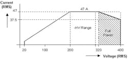
The power rating of a power supply refers to its maximum power capability of continuous output. Typically it can only be achieved at maximum output voltage. But modern AC sources can further support constant-power output range. Within the range, the unit’s maximum output current would increase as voltage decreases so that the output power keeps aligned with its rating. The width of the range depends on the product brand and model you select, so special attention is needed when choosing a product.
For example, Figure 1 shows one unit’s performance that allows 125% over-current capability, which reflects support of full output power at 80 to 100% voltage range. Other units on the market allow full output power at 75 to 100% voltage range.
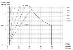
A new unit introduced recently, the California Instruments Asterion Series from AMETEK Programmable Power, employs a current enhancing technique known as iX2 current-doubling technology. It enables output current to increase up to 200% when voltage decreases to half of range, which means full power is supported at 50 to 100% of the voltage range (Figure 2).
To further push the output power limit at the low voltage end, most AC sources provide dual ranges: high-voltage range and low-voltage range, with the latter range usually half of the former. The same over-current capability applies on both ranges, so it significantly expands the full power output range. For example, the Asterion source is capable of full power output as wide as 100 V to 400 V.
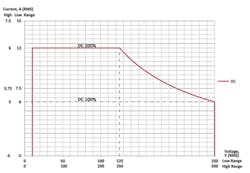
Considering the fast voltage slew-rate requirement of avionics test, it is always necessary to use an AC/DC source to cover the DC power group’s test items. That also makes it necessary to focus on the DC output V-I characteristic curves of an AC/DC source. It’s important to be noted that many AC/DC sources would have a great reduction of its power rating under DC mode. Some would claim its DC power rating is merely half of its AC power rating, adding the limit of its restricted full power output range. Such a power source could barely deliver a very limited DC output at avionics DC test voltages. Only a few power sources are capable of providing DC output power at no loss compared with its AC power rating, and supporting the same full power output range.
The Asterion series also applies the iX2 current-doubling technology on its DC mode, which makes it support full power output in a scope of 125 to 500 VDC (Figure 3).
AC 115-V power group
The nominal avionics AC power is 115 V in all versions of MIL-STD-704, and the steady-state AC voltage range for normal operation is always defined as 108 to 118 V, and in RTCA/DO-160 version F/G, it’s 100 to 122 V (Table 1). These are relatively narrow ranges.
Within this voltage range the airborne utilization equipment certainly must be capable of working in a stable manner, so the test-system power supply must provide the required power for a long duration. If your AC source is equipped with dual ranges, such as 150 V and 300 V, these test scenarios obviously would require the 150 V range for better power coverage. But if your source merely has a single range at 300 V or even higher, the actual output power capability at 108 to 118V or 100 to 122 V could be much lower than its power rating, which means you would have to select a source with much higher power rating to provide the necessary power coverage.
For example, let’s assume 20-kVA 3-phase AC utilization equipment as the equipment under test (EUT) and you want to test its normal operation steady-state performance in accordance with MIL-STD-704 or RTCA/DO-160. If we use an AC source with 150-V/300-V dual ranges and 125% overcurrent capability, it’s necessary to select a model with a power rating no less than 1.11 times that of the EUT, which is 22.2 kVA (for the 704 test) or 1.2 times that of the EUT, which 24 kVA (for the 160 test). If we use an AC source with a single 300-V range and 150% over-current capability, it’s necessary to select a model whose power rating is no less than 1.85 times. This is 37 kVA for the 704 test; for the 160 test, it’s 2 times, or 40 kVA. If we use an AC source with a single 300-V or 360-V range and no overcurrent capability under 300 V, the source used must have a power rating no less than 2.78 times, or 55.6 kVA, for the 704 test or 3 times, or 60 kVA, for the 160 test.
The abnormal operation condition also calls for steady-state test, which for MIL-STD-704 is defined as the 100- to 125-V range, and in RTCA/DO-160, it’s defined as the 97- to 134-V range. However, the EUT could be delivering different performance when the voltage falls out of normal steady-state range. It actually depends on the EUT specification definition and may not be full power. You’ll need to calculate according to actual status.
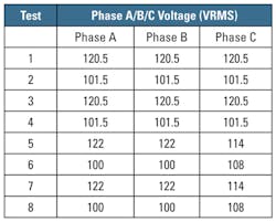
Leaving aside the power interruption (when voltage drops to 0 and there is no power output), the maximum voltage variation range under normal operation conditions is 80 to 180 V in accordance with the Normal Voltage Transient requirement in MIL-STD-704 or 70 to 160 V in accordance with the Normal Surge Voltage requirement in RTCA/DO-160. The duration at the edge voltage—80 V and 180 V in MIL-STD-704 (Figure 4) and 70 V and 160 V in RTCA/DO-160—is 10 ms and 30 ms, respectively. When running these test items, the EUT could have performance derating, but should return to normal performance after voltage recovery to normal working range.
Similarly, the voltage variation range of abnormal operation condition is even wider— 45 to 180 V in MIL-STD-704, and for RTCA/DO-160 it’s defined as 10 V for low edge with the high edge at 180 V.
To run those voltage variation test items, we need to understand the actual working status of the EUT before we can determine the corresponding power requirement. Somehow, in order to cover the voltage setting up to 180 V, those AC sources with 150-V/300-V dual ranges need to be set at the 300-V range to work. There is a procedure that calls for the EUT to show stability at 115 V for several minutes, so the AC source should be capable of providing full power to EUT at 115-V output in its 300-V range. AC sources therefore need to have a power rating at no less than 2.08 times that of the EUT to cover this requirement.
AC 230-V power group
Chapter 16.5 of RTCA/DO-160 version F/G defines utilization equipment at 230 V, so all voltage test levels should be two times of those for 115-V equipment.
For the AC sources with 150-V/300-V dual ranges, its coverage with the 300-V range on 230-V power group test is identical with 150-V range on 115-V power group test. However, there are two test protocols to run: the Normal Voltage Surge and the Abnormal Voltage Surge protocols. If the EUT is powered by 230 V, then these two items ask for test voltages up to 320 V and 360 V respectively, which exceed the 300-V range of normal AC sources. We need to use an AC source with a higher voltage range. Considering this test scenario, it’s necessary to select a source at no less than 1.39 times of EUT power rating.
DC 28-V power group
The most typical avionics DC voltage rating is 28 V. The steady-state DC voltage range is defined as 22 to 29 V in MIL-STD-704 version B through F and 22 to 30.3 V in RTCA/DO-160 version F/G. RTCA/DO-160 also defines 18 V as the lower limit for those EUTs designed to work under emergency operation (Table 2).
Since most AC/DC power supplies provide DC voltage ranges at a few to several hundreds of volts when they are set to output 28 VDC, none can deliver full power rating. It becomes meaningless to just talk about their power rating, but instead what really matters is selecting a power supply that offers the maximum output current capability at 18 to 31 V. Higher current also can be achieved by paralleling multiple units.
Correspondingly, we need to calculate the necessary current needed by the EUT. A simple evaluation is to divide its power rating by the nominal voltage, 28 V, to determine the nominal current. Then we calculate the required current at 22 V (for 704 and 160 test) or 18 V (for 160 test, emergency operation only), which should be 1.27 times or 1.56 times the nominal current. The power supply should be capable of supporting this current level.
DC 270-V power group
The steady-state DC voltage range for normal operation is defined as 250 to 280 V in MIL-STD-704 version B through F and 235 to 285 V in RTCA/DO-160 version F/G.
MIL-STD-704 also defines Normal Voltage Transients in a range of 180 to 350 V, while in RTCA/DO-160 it’s 160 to 400-V, and abnormal surge voltage is up to 425 V.
Similarly we shall need to determine the required power source parameters in accordance with the EUT power rating and different power behaviors under all those various voltage levels.
Summary
As we quickly go through the test requirements of different power groups, we can see that the test power source is required to deliver far more than simply a constant 115 VAC or 28/270-VDC output. Also, it’s usually insufficient for its nominal power rating to be merely equal with the EUT’s power. In fact, the power source should provide a broad range voltage output and usually a high-power margin dependent on its output voltage-current characteristic curve.
About the author
Wanner Huang is the business development manager of the AMETEK Programmable Power business unit responsible for PV, smart grid, space, and defense industries. After his graduation from Zhejiang University with a bachelor’s degree in 2003, he was engaged in technical support work. He joined AMETEK Programmable Power in 2010, with his office located in Shanghai.


