Download this article in .PDF format.
During 2018, the Federal Communications Commission changed the procedural requirements for EMC compliance. Previously, the emphasis was on measurements acquired by specialized, accredited test laboratories and consequent certification issued by the laboratories.
Now, manufacturers or importers of products can confirm compliance with the FCC’s requirements using a self-test, self-certification process, without having to involve any third-party or test laboratory. The previous regime featured two routes to compliance, verification and Declaration of Conformity (DoC). These are now replaced by one, the Supplier’s Declaration of Conformity (SDoC).
2018 was a transition period when either the old requirements or the new could be used to effect compliance. Since January 2019, only the new requirements should be used.
This new requirement represents a significant change in the compliance test requirements. What has now been adopted is similar to that which has been legislated in the EU since 1996. The relevant EU Directive is 2014/30/EU. This has been enshrined in law by each of the 28 individual member states so creating a ‘level playing field’ across the whole community. At its simplest level, the Directive simply states that no product should cause interference to others, or to any radio/telecoms services (emissions), and should work normally in the environment in which it is intended to be used (immunity). This immunity requirement is not required by FCC.
The purpose of this article is to describe the EU requirements so that U.S. manufacturers have an insight into how the new rules operate.
The EU basic rules
These were introduced in 1996 and apply without exception throughout the EU. Other territories such as Australia and New Zealand, have adopted the same rules:
- Manufacturers are entirely responsible for their product. This responsibility cannot be ‘delegated’ or offloaded to test labs (accredited or otherwise) or a consultant.
- There is no such thing as an ‘official’ compliance test or type test
- Note that the EU Directive states “achievement of compliance with the appropriate standards only provides an assumption of compliance with the EMC Directive.” It is for the manufacturer to perform any other tests as may be considered alternative or additional, in order to satisfy the EU Compliance statement.
- The manufacturer may use test labs and/or consultants in order to make measurements, but pass/fail judgment is the responsibility of the manufacturer
- The manufacturer must assess the results of any tests/measurements and decide whether they consider the product is compliant
- What tests are performed and how they are performed are at the discretion of the manufacturer
- Basically, the system relies on the honesty and integrity of the engineers and managers/owners at the manufacturer. In general, the system works well, with organizations from one-man-bands” to major internationals fulfilling their obligations entirely.
- The bottom line is that if the manufacturer believes that the product complies with the EMC regulations (i.e. does not cause interference and works as specified in its intended environment), then they can create the EMC Certificate of Compliance, apply the CE mark, and sell the product anywhere in the EU
- Each EU member country has an “office” responsible for maintaining compliance. This service is generally complaint-driven. In the event of a complaint by an individual or corporate body, the office is mandated to investigate, and if the complaint is upheld, the product is typically withdrawn from the market, and financial penalties may be applied.
The manufacturer’s must-do list
- Determine the compliance status of the product using appropriate tests and facilities. The manufacturer may involve third-party test laboratories, but self-testing is entirely acceptable.
- Create the Supplier Declaration of Conformity (SDoC). The supplier must be based in the U.S. If the product is imported, the importer becomes the responsible party and must obtain a copy of the compliance test results and certification from the original manufacturer, or perform the appropriate testing in the U.S.
- Label the product so that it can be uniquely identified and related to the SDoC
- The FCC logo is now optional
- In the user manual or instructions, add any pertinent information regarding compliance. (for example, installation or cabling requirements)
- The technical information related to compliance tests and results, together with assessments and conclusions, must be kept on file and made available to the FCC on request
Results in the EU
Does the system work? Yes, surprisingly well.
Benefits
Self-testing can bring cost savings. The key parameter is the number of products that may need certification in a typical year. If only one product per annum is likely to need certification, the lowest cost option lies with use of test labs. If many products per annum need certification, self-testing will bring cost savings. The crossover point here in the UK lies in the region of five or six products per annum. This assumes both emissions and immunity testing as required for CE compliance, and allows for the higher cost of immunity test equipment. For FCC compliance, the crossover point is lower, typically three to four products per annum, due to the lower equipment costs involved when not including immunity testing.
The above benefits consider only the crude accounting costs. Actual benefits include:
- The ability to test during design/development phases, with consequent avoidance of later revisions and re-tests
- Reduced time-to-market
- No delays caused by lack of test lab availability
- Travel and transport costs avoided
- Increased EMC expertise and capabilities as staff become practised at EMC testing and evaluations
These benefits may appear as incidental, but in fact they can bring results far more significant than just the obvious accounting figures.
How hard is it?
If we consider just emissions, there are two basic measurements required: Conducted emissions and radiated emissions.
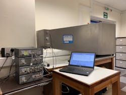
Conducted emissions is easy. For power cables, a LISN connected to an EMC analyzer or receiver is required. For other cables (data, sensors etc.), these only need checking if they are more than 3m long. No need for screened rooms, tents or anything special. Do the test on your own workbench.
Radiated emissions need more consideration. In principle, it’s easy. Just set up an antenna 3m from the product and measure the results on your EMC analyzer or receiver. In practice, there are two problems with this: Ambient noise, and test site calibration. These are often mistakenly linked, but they are entirely different and separate issues which require different solutions.
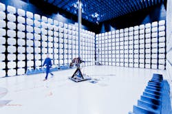
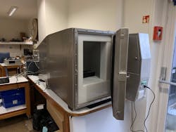
For ambient noise, a ‘screened’ environment such as a test cell or anechoic chamber provide the obvious solution. Note that ‘screened room’ is not suggested as a solution. Screened rooms should not be used because of the internal reflections which will create massive measurement errors. A cost-effective alternative is to use an ‘open’ site with a system which can measure and then subtract the ambient noise from the emissions from the device-under-test (DUT). This system works well on moderately noisy sites, but strong local sources such as transmitters may overwhelm the receiver or analyzer. As a solution: If the DUT is portable, find a quieter site.
Test site calibration is the major source of measurement error in any radiated emissions measurement. Manufacturers are inevitably restricted in their choice of site due to space and budgetary restrictions. Typical sites are a manufacturing area, loading bay, conference room, car park, or something similar. These sites will all suffer from the proximity of metal surfaces which will reflect RF. Reflected RF will interfere with the measurement and the result is a site that does not behave like a true OATS. If, however, a known and calibrated source of RF is substituted for the DUT, the characteristics of the test site can be measured. A correction factor can then be calculated so that when the DUT is measured, the results are corrected so that they appear as though they had been measured on a good 3m OATS site.
The process
The ERS is a comb generator, with a frequency interval of 2MHz. Each 2MHz peak is measured and documented, a total of 485 points in the range 30MHz to 1000MHz. Each ERS is traceable to the master EMC OATS in the UK (NPL, Teddington). It is supplied with the radiated emissions data as measured at 3m. If ‘your’ site was as ‘good’ as NPL, the measurements would agree with the supplied data. Inevitably, the results will differ. At each 2MHz point, the emission level from the ERS is measured and the effect of any ambient noise is also taken into account. This measured level is then compared with the calibration data, and a correction value can then be calculated. If for example, the measured value was 49dBuV, and the calibration data from that frequency was 57dBuV, then your site is reading 8dB low, so a correction factor of +8dB should be added to any DUT measurements at that frequency. The process is applied to all 485 frequencies.
When measuring the DUT, the ambient noise is first canceled, then the site correction factor is applied.
Measurement uncertainty
A properly configured test bench and a decent EMC analyzer or receiver should be able to deliver conducted emission results with the 4dB uncertainty margin that any accredited test lab would apply. There are no requirements for screened rooms, just a ground plane under the nonmetallic test bench, LISN bolted to the ground plane and short cables from the LISN to the DUT.
Radiated emissions are not so easy. Note that even accredited test labs will not quote better than 6dB uncertainty. Inherent variances are due to DUT cable positioning and orientation, coupling to chamber or test cell structure and (for mains-powered DUTs) local mains supply impedances and imbalances. However, the aim of any self-test process is to match OATS setup conditions as far as practicable. The ERS is a very significant aid in this respect. Without some site calibration, the uncertainty is ‘off scale’, but by using an ERS, and rigorous process, uncertainty should be better than 10dB. An excellent alternative is to use a similar product which has been measured at a test lab and to use this to characterize your site.
In summary
EMC measurements are often portrayed as difficult, specialist, and even obscure, but in reality, they are just another topic that we engineers need to “learn.” There are many sources of good information on the web related to test techniques. Setup, configuration and procedures are important, but these are straightforward. It helps to have receiver/analysis software that is simple and intuitive to use, designed for occasional users, rather than full-time test lab technicians. It also helps to have an instrumentation supplier prepared to advise and provide guidance on the test procedures.
David Mawdsley is managing director of U.K.-based Laplace Instruments. He has been involved with the development of EMC compliance test and measurement techniques since 1995. His particular focus has been on fully integrated systems that can be used by manufacturers to achieve self-test, self-certification of commercial products.


