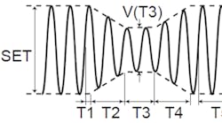
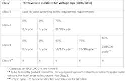
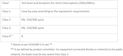
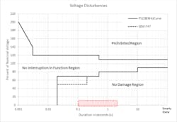
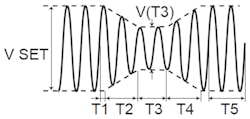
It seems that everyone is testing IEC61000-4-11 in order to obtain CB certification and international certification (CE marking etc.). The IEC61000-4-11 standard specifies voltage dip, short interruptions, and voltage variation immunity tests. The class determines test level and duration. Regarding judgments, the level of performance standard required is different, depending on each standard required of EUT.
Is it enough to do this test as immunity tolerance in the actual field? Not in my experience. This is especially true if it is intended to be used in countries and regions with insufficient power infrastructure. In the worst case, the equipment will fail. So, I recommend that you test thoroughly before releasing the product to make sure that the problem does not occur.
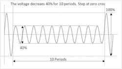
Voltage dip
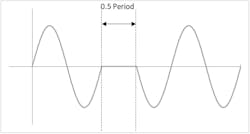
Short interruptions
Tests at 0% testing level for voltage dip are 1 cycle at maximum for both Classes 2 and 3. Converting this period to time results in 20ms (@ 50 Hz).
Next, looking at the duration of short interruptions, both Classes 2 and 3 have 250 cycles (@ 50 Hz)/300 cycles (60 Hz). Converting this period to time gives 5s. Testing at the 0% test level of the voltage dip is up to one cycle in both Classes 2 and 3. Converting this period to time results in 20ms (@ 50 Hz).
Next, looking at the short break period, both classes 2 and 3 have 250 cycles (@ 50 Hz)/300 cycles (60 Hz). Converting this period to time is 5 seconds. Have you confirmed that your equipment will not break if a power interruptions occurs for 20ms to 5s?
Actual condition of short interruptions
There are many momentary power interruptions over 20ms. In addition, it may occur intermittently, and the total time exceeds 20ms. What happens to your equipment in this case? In the worst case, the inrush current at the time of power recovery may cause the destruction of diodes and MOSFETs in PFC circuits and DCDC circuits, burnout of PCB patterns, burnout of fuses.
During normal startup, the input current is limited by the inrush current prevention circuit or the soft start function to prevent the inrush current from flowing into the capacitor, but these functions may not work during power recovery, and an overcurrent may flow.
In addition, in the DC/DC circuit, the voltage decreases because the charge stored in the capacitor inside the power supply decreases at the time of a power failure. Since the power supply controller tries to maintain the output by maximizing the PWM duty, the control response may not be in time at the time of power recovery, and an overcurrent may flow.
In the case of a simple protection circuit such as a power thermistor, intermittent ON/OFF may reduce the resistance and may cause an overcurrent. Even if failure does not occur, differences in the timing of individual circuit shutdowns may cause equipment to malfunction or fail to operate properly. In order to prevent them, it is necessary to monitor the input voltage and internal power supply voltage at appropriate timing, and reset the entire system to prepare for recovery.
The power line disturbance simulation function
The test uses an AC power supply for testing. Some products have application software for 4-11 standard tests, although tests can only be performed on the main unit.
You can test for voltage dips (pops) & short interruptions with the following steps:
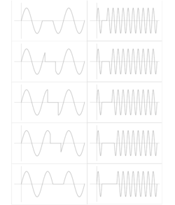
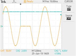
That's it for setting. After that, just turn on the output and run the simulation. With the above contents, the output waveform when simulation is performed is as follows:
The easy programming
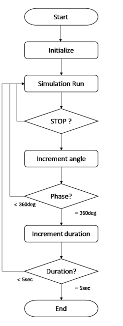
- Sample program flow and code
- Change both the immersion time and angle at the time of short interruptions to 0, 45, 90, 135, 180, 225, 270, and 315 degrees. This is to test at the point where the current value is maximum.
- After initialization, the program performs power line disturbance simulation, monitors the status by polling, and waits for the status to stop
- Then, change the phase and let it repeat until it reaches 360 degrees
- When reaching 360 degrees, increase the immersion time and run as a phase of 0 degrees. Repeat this.
- It is recommended that you run this test with the test object output at maximum load. Proceed while checking that the device under test does not break down or malfunction.
Summary
Takemi Iguchi is a technical advisory manager at Kikusui America, and has been with the company’s development division for more than 19 years.
