Download this article in .PDF format.
In recent years, problems that affect the stable operation of grids, such as voltage fluctuations and the generation of surplus power from solar and other renewable-energy power sources, have become prominent. In order to stabilize the grid, it is necessary to adjust the power generation.
V2G (vehicle to grid) technology provides a way to adjust the grid to suppress fluctuations by utilizing EV batteries. Also, peak power can be shifted by storing surplus power and supplying it when demand reaches its peak. V2G is expected to be one of the technologies that can solve the problems of renewable-energy power generation.
By using V2G technology to control charging/discharging of multiple EVs, V2G can be used as a resource for a VPP (Virtual Power Plant). Because a VPP can balance power and demand without establishing large-scale power-plant infrastructure, its use has been studied in several countries, and empirical and commercialization studies are underway. As renewable-energy power generation, including solar power generation, increases, VPP construction using V2G is expected to expand in the future.
This article describes a test solution for V2G.
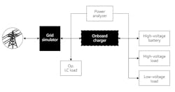
With V2G, power is supplied from the vehicle to the power grid. The power output from the vehicle is controlled on the grid side and is expected to be used for the frequency adjustment and demand adjustment of the power system. Figure 1 shows the simulation of the power grid for onboard charger evaluation.
Since a general switching-type AC power supply cannot sink current, a resistive load device for discharging has traditionally been required to verify the operation during regeneration. The use a grid simulator capable of 4-quadrant operation eliminates the need for discharge resistors. In addition, because energy is not consumed as heat by the resistors but instead is regenerated to the grid, power consumption can be reduced.
A programmable power supply able to serve as a grid simulator (such as the one shown in Figure 2) can provide full 4-quadrant operation with regeneration of up to 100% of the output power. The voltage, phase angle, waveform, and impedance can be changed for each phase. It offers power-line disturbance simulation (voltage dips, short interruptions, and voltage variations) and supports testing in accordance with IEC61000-4-11.1 It offers arbitrary and harmonic waveform generation and features an isolated analog programmable interface with each phase. It is also easily used in a hardware-in-the-loop (HIL) system.
Bidirectional-type onboard chargers require functional testing of tripping requirements and ride-through requirements in accordance with IEEE 1547-2018.2 They are designed to meet all bulk system needs and power-system reliability and power-distribution-system reliability needs. By using a grid simulator, it is possible to easily create an environment for performing the required tests.
Battery simulation
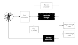
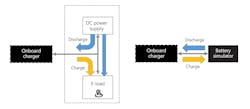
Previously, batteries were simulated using a combination of power supplies and electronic loads. However, to switch between charging and discharging at high speed, it was necessary to supply current from the power supply to the electronic load during charging. Electricity was wasted, and the power capacity of the electronic load needed to be increased, resulting in larger equipment and higher purchase costs. In addition, if the electronic load was not regenerative, all the charging power became heat. Therefore, there was also a cost for cooling the exhaust heat. These problems can be greatly improved by using a regenerative battery simulator (Figure 4).
EV simulator
A simulation solution can simulate an EV battery without the need for actually connecting a car. It consists of DC power supply, electronic load, communication controller, and control application software. Simulation is useful when it is difficult to build an actual vehicle environment, such as might be required for electric-vehicle supply-equipment (EVSE), vehicle-to-home (V2H), and V2G power-conditioner operation tests and production inspections. Simulation is also be useful when it is difficult to adjust the car parameters of each automobile manufacturer.
It is difficult to use an actual battery for each vehicle model due to various voltage-current characteristics and impedance characteristics. In such cases, you can reproduce and test each condition using simulation. In addition to normal areas, abnormal area tests can be safely verified.
An EVSE simulator can simulate the EV quick charger specified in the standard specification of the quick-charging station for electric vehicles (CHAdeMO). The simulation range varies depending on the component, but for the full set, the time specified in the CHAdeMO standard can be changed. GB/T charging and COMBO charging are also supported. The charging method can be selected, and multiple charging methods can be selected.
By using this, you can easily test abnormal conditions during EV charging. For example, the timing and compliance time specified in the CHAdeMO standard can be changed, or the control line abnormality simulation can be executed at any timing, and the abnormality related to the soft error can be simulated. Tests can be performed more efficiently than by using actual machines.
Author bio
Takemi Iguchi is a technical advisory manager at Kikusui America and has been with the company’s development division for more than 19 years.
REFERENCES
1. IEC 61000-4-11:2004+AMD1:2017, “Electromagnetic compatibility (EMC)—Part 4-11: Testing and measurement techniques—Voltage dips, short interruptions and voltage variations immunity tests.”
2. IEEE 1547-2018, “IEEE Standard for Interconnection and Interoperability of Distributed Energy Resources with Associated Electric Power Systems Interfaces.”


