Addressing Test Challenges for Advanced Vehicle Power Electronics
The automotive world is racing into a disruptive future, with uncertainty being presented to the industry from a variety of directions. The power electronics aspects of vehicles are among the most important, as they impact every subsystem. Beyond the “ordinary” issues such as the introduction of advanced topologies, materials, and core technologies, there are also societal issues of energy markets and the current environment engendered by COVID-19.
Creating a design process today for automotive development must not only address the issues of integrating and verifying multiple advanced technologies, it must also deal with the very real situation where road testing possibilities are limited during the global COVID-19 outbreak. Proper development and test procedures will not only ensure the best possible solution, it will also significantly reduce the amount of hands-on testing.
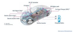
Modern vehicles are a complex gestalt of advanced technologies, serving the array of transportation applications the market demands. These various functionalities are provided by next-generation subsystems, and each of these subsystems have their own design and development requirements (Figure 1).
The common thread in all of these vehicle systems is power management. Each of these systems present their own test and measurement challenges to the engineer. Only by using the best solutions available can these systems be properly integrated and optimized. These vital systems are not only limited to the car, but by necessity must include the power grid and available EV-charging infrastructures.
Programmable power supplies and programmable electronic loads are a valuable tool in this design and optimization process. This article will discuss some of the challenges being addressed by automotive electronics designers, and how the newest generation of test equipment is up to enabling the task.
EV Charging Challenges
One of the biggest visual symbols of the migration from fossil-fuel to electric vehicles is the switch from having to gas up, to having to charge up. Charging systems are a challenging aspect of our growing vehicle infrastructure due to the massive amounts of current that need to be transferred in the most expedient and efficient manner possible. Beyond the fixed charging stations being created, there are also onboard chargers so that EVs can serve themselves.
When it comes to defining external charging systems, there are two major specifying groups. The Society of Automotive Engineers (SAE) sets three levels: Level 1 covers the power range from 1.44kW to 1.92kW, at 12A to 16A at 120VAC or 230VAC. Level 2 ranges from 3.1kW to 19.2kW, at 15A to 80A in polyphase operation. Level 3 is from 120kW to 240kW, at up to 400A, at 300Vdc to 900Vdc.
Plug-in hybrid (PHEV) and battery electric (BEV) vehicles have battery voltage standardized at approx. 450 V with a trend towards higher voltages, as this supports faster charging times and enables lighter cabling within the vehicle. In the case of the Porsche Taycan, it has a system voltage of 800V. The charging time from 5% to 80% state of charge is 22.5 minutes under ideal conditions (with an external charger), and the maximum charging power (peak) is 270 kW.
The International Electrotechnical Commission (IEC) calls for four power modes. Mode 1 is for slow-charging from a regular electrical socket, be it single- or three-phase. Mode 2 is for slow charging equipped with an vehicle-specific protection system, and Mode 3 is for either slow- or fast-charging using a multi-pin socket with control and protection functions (according to SAE J1772 and IEC 62196 standards). Mode 4 is for fast charging using a special charger technology such as CHAdeMO or other systems that enable seamless communication between the car and the charger.
The Combined Charging System (CCS) covers charging electric vehicles at up to 350 kilowatts. This charging environment encompasses charging couplers, charging communication, charging stations, the electric vehicle, and various functions for the charging process, such as load balancing and charge authorization.
Inside the vehicle, an on-board charger (OBC) is used to charge the traction battery. As long as the vehicle charging infrastructure isn’t ubiquitous, there will always need to be a robust charging alternative onboard. Perhaps like the spare tire, this subsystem will fade in importance as time goes on, but for now it is a vital subsystem with very large power, safety, and performance requirements.
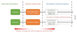
Utilization of the latest generation of bidirectional, regenerative programmable power sources and loads provides a highly efficient means for conducting these tests. An example of such a bidirectional power solution is the Elektro-Automatik PSB 10000, a 4U 30 KW power supply and load in one. It has an AC input range from 360 V to 528 V, for operation on 400 V and 480 V grids.
The flexible, power-regulated DC-AC stage offers various protection circuits, with an intuitive TFT touch panel with display for values, status, and notifications. Features include remote sensing with automatic detection, a galvanically isolated, analog interface, and an integrated function generator. Interfaces include a USB port as well as optional digital interface modules. A typical setup using a bidirectional power solution is shown in Figure 2.
Electronic loads typically dissipate the power transferred to them as heat, but it can add up, especially in test applications where multiple systems are tested in parallel. Because of the need to remove the heat from the electronic loads, they are often large, with significant forced-air or water circulation to cool them. This normally leads to an increase in test system cost, size, and HVAC requirements, to control and remove the heat from the facility.
Integrated regenerative source/sink solutions can seamlessly move from sourcing current sinking current without external circuits, or synchronized programming of a separate power supply and electronic load. Such integration enables a testing regimen that is not only accurate and effective, but also energy-efficient and cost-effective.
Vehicle testing standards
In every field of application engineering, there are standards, regulations, and guidelines on how the application under question must be served. In the area of life-critical application spaces like medical and automotive, this regulatory effort is an important aspect of regional markets and the governments that oversee them.
Among the various governments involved in the regulation of their respective economies, the German auto manufacturing industry leads in defining the tests for electric and hybrid electric vehicle electronic systems. Their LV123 is an organized listing of test requirements for all German automotive OEMs. The systematic approach and transparent definition of test parameters enable the exchanging of qualification results among participants, and comparability of product qualifications between OEMs.
LV123 covers high-voltage (HV) systems in a methodical manner. Table 1 summarizes the test limits as spelled out in LV123.
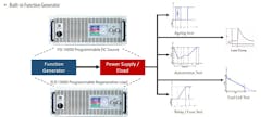
Many of these tests require application of the test equipment’s arbitrary waveform generation feature. Arbitrary waveform generation is not a new concept, but these new automotive testing standards are extending the with respect to voltage and current levels and voltage dynamics. Figure 3 is representative of the types of programming required.
Such stringent electronic testing requirements demand testing solutions to address them in an efficient and cost-effective manner. One such solution is the use of bidirectional power supplies, which offer multiple advantages useful to the application. For example, not only can such systems achieve the high voltages required, it is possible to achieve smooth current switching without notch at the cross point during switching, overshoot, or undershoot of the current waveform.
Repeated tests can be performed using bidirectional power supplies, without worrying about overcharging, over-discharging, or deterioration of the rechargeable battery under test. A regenerative power supply can also be used as a CV/CC or a CV/CV power supply. The reuse of power also opens the door to money and energy savings.
Looking forward
With energy efficiency at a premium for those who need to perform high-power tests, using bidirectional power testing solutions like the PSB 10000 enable a significant reduction in the cost of operation and ownership, while also increasing reliability and performance. The advanced capability of a built-in regenerative electronic load is of great value in meeting the newest automotive electronics testing requirements.
For more information visit www.elektroautomatik.us


