The fundamental idea for the cathode ray oscilloscope dates all the way back to 1897. Yet the triggered scope with a calibrated time base had to wait until Howard Vollum returned from England, where he’d worked on fire-control radar. In 1946, Vollum founded Tektronix to sell scopes that would trigger repeatably on a precise voltage level of the input waveform and provide calibrated amplitude and timing measurements that could be read from a graticule over the face of a CRT.
This file type includes high resolution graphics and schematics when applicable.
Scopes from Tek and Hewlett-Packard (among a few others) then became the gold standard for circuit designers, bench engineers, and skilled technicians. One of the things that characterized those instruments and their successors over more than half a century was that learning to use one properly was a little like learning to fly a small plane. It wasn’t all that hard, but it took some engineering knowhow and practical experience—and a good teacher—before you were adept.
Over the years, scopes followed the needs of engineers to make faster and more sensitive measurements, to go beyond the time domain into the frequency and data domains, to capture tiny glitches, and to store and play back events. But they primarily remained general-purpose instruments, and users needed considerable knowledge of the application area being investigated to understand what the scope was trying to say.
That’s been changing over the last few years. Downloadable firmware has made scopes a lot more versatile in terms of how well they can concentrate on the measurements needed for specific tasks. These days, it’s all in the software.
Ease Of Use Takes Center Stage
Test and measurement vendors often will assert that their particular instrument sets the standard for intuitive operation and ease of use. Most of today’s innovation around tools for validating or debugging electronics designs isn’t about speeds and feeds, but more “touchy feely” factors like usability, productivity, and intuitive operation. While it’s easy to dismiss improved usability as a significant development, the day-to-day requirements placed on design engineers suggest that it has emerged as a critical feature.
First off, there’s the question of emphasis. Design engineers first and foremost are designers, not necessarily test and measurement experts. Time spent building test fixtures, writing MATLAB scripts, or struggling with complex, convoluted user interfaces all equate to lost time doing what they are really good at—designing.
Along the same lines, economic pressures and budget cuts mean today’s engineer must be a jack of all trades. The engineer in the past who could focus on digital design now must get involved in validating power supplies or sorting out wireless local-area network (WLAN) interference problems.
To make those different tasks easier, automated measurements and test suites are becoming increasingly important. From power analysis measurements like switching loss and safe operating area to common measurements on an RF radio like occupied bandwidth and channel power, these automated measurements make highly complex measurements simple and repeatable even for engineers whose primary jobs revolve around design.
Using the various tools, designers can take on many common tasks such as validating the operation of an embedded power supply or checking the functionality of an integrated wireless radio module without complex programming. Given the importance of usability, automation, and versatility for many designers, advanced test suites now are becoming available on more affordable instrumentation.
Ultimately, electronics test instrumentation is a means to an end—useful insight into what’s going wrong with a design, to validate compliance with a specification, or to find the stress points that cause failure. The easier and faster the “time to answer” is achieved, the better. This will continue to be a key area of emphasis in the years ahead.
The Importance Of Rapid Analysis
Following the incorporation of greater computing power in digital oscilloscopes, vendors have pulled increased measurement functionality into these instruments. Through software systems for compliance testing, full “push button” pass/fail analysis of popular buses such as USB and Ethernet is now possible.
While some measurement reconfiguration and repetition is required, the process is very automated. This often frees the user from needing to be an expert in any particular bus specification. Because so many buses are extant today, it can become impossible for someone to retain this broad and deep level of bus expertise.
Additionally, these software packages can even decode and provide compliance or signal quality tests for RF signaling. Near-field communications (NFC) is a standard that can be difficult to ensure interoperability on. Utilizing an automated software package can provide confidence and consistency to the evaluation of these signals.
Now that the automation of common digital standards has been incorporated into modern oscilloscopes, the next frontier of complex new problems arises. The introduction of these very same RF signals and the high-speed signals in many digital standards brings about yet another challenge for designers in the modern era.
The high switching rates of these signals and the power levels of some RF signals can cause significant electromagnetic interference (EMI) issues. The problems created can range from in-system issues such as coupling into nearby and lower power traces to EMI compliance standards issues.
One example might be a buck converter (step down) power supply operating at 600 kHz that is taking a 12-V input and creating a 1.8-V supply to another part of the system. Nearby signal traces might see coupling from the harmonics of this supply during certain load conditions. If a test engineer only sees the disturbance and cannot trace back to the source, how will the designer modify the design for proper functionality?
Another example is FCC Class-B radiated emissions between 30 MHz and 1 GHz at 3 meters. These emissions cannot exceed 40 dbµV/m (or 54 dbµV/m, depending on the frequency band). Often, engineers don’t think about the EMI issues during the debug phase. So, what is to be done when the test report comes back with a failing result?
Enter the next advance in oscilloscope technologies. Utilizing hardware-based fast Fourier transform (FFT) technology and highly sensitive front ends with high dynamic range, some modern oscilloscopes also can function as a spectrum analyzer with perfect correlation to the time domain. This technology allows for both of these issues to be understood, debugged, and resolved.
The major contribution allowing this has been the movement of FFT analysis into hardware in the oscilloscope architecture. This creates a high update rate or “feel” when using an FFT to give the impression of a live spectrum update. Using an oscilloscope like this provides multiple benefits over a traditional approach using a separate oscilloscope and spectrum analyzer.
Due to the broadband nature of the oscilloscope, multiple gigahertz of spectrum can be viewed at once. Transient and intermittent signals at varying frequencies then can be seen and analyzed at the same time. You might not always know where specifically to look within the spectrum. With a high-update-rate FFT, you can look everywhere.
Interference between harmonic signals or non-harmonic anomalies can be quickly identified and traced back into the time domain. This could allow for fast troubleshooting of a power supply that is creating distortions in nearby signals.
Stopping on an event utilizing frequency masks can allow for time-relevant debug of intermittent events and even the ability to go back in time to evaluate root cause events. This might be utilized when a rare but significant event turns on and causes an EMI violation in the chamber.
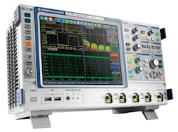
Modern oscilloscopes such as the recently introduced RTE series and the popular RTO series from Rohde & Schwarz are bringing measurements like these to oscilloscopes, starting at 200 MHz (Fig. 1). Important considerations are the type of FFT being used, along with the bandwidth needed for the analog measurements and the frequency domain measurements needed.
When Multiple Serial-Data Protocols Attack
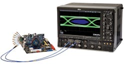
The days when designers worked with one or two serial-data protocols for any given project are largely over. Now, system designs often integrate a host of serial protocols: SATA for the disk drive(s), USB for external connectivity, DDR for memory interfaces, and a display bus such as DisplayPort (Fig. 2).
For the beleaguered design team, this necessitates validation of all these different standards. The validation of even a single serial-data interface is a tedious and time-consuming process, involving setting up test equipment for each of a long series of tests, plugging and unplugging cabling, soldering down probes, and so on. Now multiply that test load by two, three, or four times, and the need to automate the validation process quickly becomes obvious.
Thus, automated compliance testing has been one of the most important trends in test and measurement in recent years. Standards organizations for certain serial protocols, such as USB, PCI Express, and SATA have very strict “logo programs” in which they specify a set battery of tests that an interface must pass before they will permit their logo to grace the end product. Without that logo, you will not be shipping your end product with that interface. Testing is done at workshops where engineers must prove adherence to the specification.
With some other protocols, a test specification exists but leaves compliance up to system integrators. In such cases, compliance testing is still a necessity, especially for manufacturers of subsystems that integrate some serial protocols (DDR and Serial Attached SCSI, or SAS, for example) so system integrators have a performance baseline for comparison.
Given the compelling need to validate serial interfaces, automated compliance testing continues to grow in popularity. Once a compliance test package such as Teledyne LeCroy’s QualiPHY is installed on a Teledyne LeCroy oscilloscope, compliance testing becomes a pushbutton operation.
Distinct advantages emerge from the adoption of automated compliance testing. First, there is a dramatic reduction in the time and effort required for a given battery of tests. For each test, the software presents the user with a connection diagram to ensure the setup is correct. Second, it would be quite a challenge for an engineer to become an expert in the validation of multiple serial-data standards. Automation eliminates that requirement, as the software encapsulates all of the relevant tests for a given standard as well as the specified measurement limits for each test.
Automation ensures uniformity in testing no matter where in the world it takes place. This promotes collaboration between test and validation engineers for multinational or global enterprises.
Then there is the matter of documentation, another tedious aspect of compliance validation. The automation software fully documents measured values as well as the spec’s limits for each test in the suite, comparing measurements with the limits for a pass/fail result. The software also attaches an accompanying screen capture for worst-case measurements.
With ever-rising bit rates, error margins for serial interfaces continue to shrink. Compliance testing and interoperability between systems require designers to validate devices for timing, jitter, and other critical parameters. The revolution in test automation for compliance testing goes a long way toward ensuring first-pass design and debug success.
Evolving With New Technology
The way we interact with devices is constantly changing because we live in a software-oriented world. Embedded software now defines smartphones, set-top boxes, and even automobiles. Now, the challenge is keeping up with the pace of innovation and its resulting complexities.
Two decades ago, testing a phone meant getting a signal. Today the design, test, and production of a mobile device involve an entire ecosystem of functionality, applications, and technology resulting in a different approach to test.
Devices under test (DUTs) are moving away from single-purpose, hardware-centric entities with limited capability to multipurpose, software-centric entities with endless capability. This has changed the test landscape over the past 20 years by forcing the switch from traditional instruments with vendor-defined functionality to a software-defined architecture, allowing user-defined measurements and analysis in real time. With a software-defined approach, the commercial off-the-shelf technology powering the latest DUTs can power your test system in the same way, optimizing your test architecture for years to come.
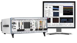
The software-defined philosophy embraces an architecture that combines PXI, a modular standard, and National Instruments LabVIEW system design software. Through this approach, you can use technologies such as multicore microprocessors, user-programmable FPGAs, PCI Express hardware, and system design software to meet the flexibility and scalability demand for future test and measurement applications.
PXI, or PCI eXtensions for Instrumentation, is an open specification governed by the PXI Systems Alliance (PXISA) that defines a rugged, high-performance platform optimized for test, measurement, and control. Since PXI is based on PC technology, it takes advantage of the evolution in this space, as with the introduction of PCI Express in 2005.
Moore’s law enabled rapid growth and development in the PXI instrumentation space, driving the use of multicore processors, PCI Express buses, FPGAs, and analog-to-digital converters (ADCs). Automated test systems that apply Moore’s Law through the use of software-defined architecture commonly see improvements of 10 times or more in size, cost, and power reductions.
In 2007, Qualcomm saw 10 times faster performance improvements compared to its traditional approach by adopting PXI hardware and NI LabVIEW. As its test needs evolved in 2012, Qualcomm augmented its automated test system with a user-programmable FPGA solution (NI PXIe-5644R) from National Instruments that saw a twenty-fold improvement of test times over its previous PXI solution and up to 200 times compared to its traditional instrument solution (Fig. 3).
The software-defined instrumentation approach uses open software and modular hardware with key elements (multicore CPUs, user-programmable FPGAs, PCI Express, data converters, and LabVIEW system design software) to address the most demanding challenges. As instrumentation evolves to meet newer standards, more complex protocols, and higher bandwidths, these tools provide a foundational platform of a test approach that can stand the test of time.
Pre-Defined Measurements
Wireless devices require fast, accurate testing, from basic power and distortion measurements to advanced modulation analysis. The complexity of modern wireless systems and signals complicates RF measurements in terms of both measurement setup and interpretation.
One of the largest challenges faced is the need to reduce the amount of time it takes to set up a test system while incorporating test algorithms that are in line with the latest standards, can meet the most stringent test requirements, and don’t require users to rewrite code or relearn testing procedures.
From design and simulation software to R&D prototype performance testing to high-volume manufacturing, Agilent provides pre-defined measurement solutions, including applications with one-button test capabilities.
For example, the 89600 vector signal analyzer (VSA) software and X-Series measurement applications provide pre-defined measurement algorithms, standard setups, a range of graphic and tabular measurement displays, and confidence in measurement results across benchtop and modular signal analyzers throughout the product development lifecycle.
The 89000 VSA software user interface is optimized for the measurement flexibility and power needed in the design and troubleshooting of wireless products. It also lets users perform multi-channel signal analysis and demodulate more than 75 signal formats.
The standards-based X-Series measurement applications focus on common and essential measurements. They are well suited to design verification and manufacturing applications where the essential RF tests are well defined and where speed and simplicity are paramount.
The algorithms upon which both software platforms are built are generally developed in close cooperation with end users and their devices to ensure their validity and the specificity and usefulness of their results, as well as the displays created from them.
To perform reliably over time, these algorithms must be validated on example signals, including any changes in signal definition or modes as standards evolve. The algorithms also must be regression-tested to ensure that related software developments have no inadvertent effects.
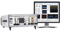
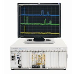
Agilent tests the core algorithms to ensure that different hardware platforms provide comparable results that allow engineers to troubleshoot and optimize designs even when the hardware acquiring the signal may be different. Agilent’s M9393A PXI express performance vector signal analyzer facilitates design characterization through the use of the pre-defined tests (Fig. 4).
The Agilent software works with test equipment such as the M9393A PXI VSA. The pre-defined measurement capability provided by the combination of hardware and software reduces the need for re-training and re-programming and simplifies measurement setup, minimizing user errors in both measurement setup and interpretation, enabling users to adapt more quickly and easily as standards evolve and as new ones are introduced.
An Alternative Paradigm
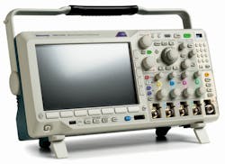
Tektronix changed the rules of the game. The company developed its most recently announced scope for the general-purpose area by adding it to its mixed-domain line (while shaving the price). The MDO3000 series portable/bench scopes also embody a spectrum analyzer, an arbitrary function generator, a logic analyzer, a protocol analyzer, and a digital voltmeter/counter (Fig. 5).1
Don’t need all that? These tools remain latent until you unlock them with tiny dongles. There’s a single base price and separate prices for each dongle. (Tek calls them “chicklets,” because, if you remember the candy-coated chewing gum, that’s about how big they are.) The new thing is that each chicklet will only activate one instrument at a time, but they’re portable. A company or a college can have a number of mainframes (which are about the size of a lunchbox) and a smaller number of, say, spectrum analyzer chicklets. And, yes, there are security protocols that make the chicklets replaceable if lost, but useless in the wrong hands.
