Practically everything you design these days includes some kind of serial interface. In fact, it’s hard to name something without a serial I/O port. Some of the more popular varieties are RS-232, RS-485, USB, I2C, CAN, SPI, and Ethernet. JTAG with boundary scan is another serial port.
At some point, you’ll need to test that interface. Before testing, though, you should consider these five key factors:
1. Get a copy of the standards. Most serial interfaces have formal standards that define the physical-layer characteristics as well as any accompanying protocol. You will need to know whether your interface meets the specifications in the hopes of ensuring interoperability. Beyond contacting the standards body, you should check for a supporting organization (an alliance, forum, or consortium) that promotes and enhances the standard. Many offer detailed testing procedures that help save much time and grief.
2. Acquire the right test gear. An oscilloscope is still the most important test instrument for serial-interface testing. Most scope manufacturers also provide special software or hardware designed to facilitate the testing of the most common serial interfaces. Don’t forget the probes, though. Some high-speed interfaces need special probes in order to be tested reliably. In addition, multiple probes are needed for differential transmission line testing. On top of that, a proper pulse generator is needed to produce a test pattern or words, such as an arbitrary waveform generator or one that produces pseudo random pulse trains. Another option is a protocol or network analyzer that will capture a serial stream, analyze it, and display the results.
3. Check the bit error rate (BER). BER—a key measure in most high-speed serial tests—represents the number of bit errors that occur for a given number of transmitted bits. Some higher-quality interfaces demand BERs of 10-12 or even 10-15. This is a great overall test because it measures the quality of the serial link medium as well as characteristics like noise and crosstalk. Bit-error-rate testers (BERTs) are also available to simplify and speed up the process.
4. Verify the jitter. Jitter is the time displacement of the binary signal’s leading and trailing edges, or something like a low-deviation frequency modulation of the pulse signal. It’s caused by clock instability, phase noise, or some interference. When the jitter time begins to be a large percentage of the bit time, jitter becomes an issue due to timing problems and bit errors. Multiple types of jitter exist, such as period jitter, cycle-to-cycle jitter, long-term jitter, and a few others, so check the standard to know what is important. The unit of jitter measurement is peak-to-peak time, usually in picoseconds. To measure jitter, its variation must be determined by averaging hundreds or thousands of sequential unit intervals (UIs). This provides a root-mean-square (RMS) jitter value. Long-term jitter averages over 10K of UIs.
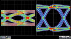
5. Use eye patterns. Eye patterns are scope displays of one or two periods of a test sequence’s overlapping serial pulses. Again, one bit time is otherwise referred to as a UI. Eye patterns are very meaningful tools for measuring attenuation, bandwidth limitations, and noise. Some standards have a formal eye mask that can be used to measure the signal integrity required to meet the specifications.
BER, jitter, and eye-pattern tests are primarily used for very-high-speed interfaces (>100 MHz). Testing for lower-speed interfaces—a much easier task—often ignores these three factors.
Check with your scope manufacturer for serial-interface test options. Most manufacturers, such as Keysight (formerly Agilent), Teledyne LeCroy, Tektronix, and others, offer a wide range of accessories and options. Test-instrument companies like Anritsu and Rohde & Schwarz also have selected test products available for certain serial interfaces.
Fiber-optic serial interfaces are a special case, and usually require special equipment for electrical-optical conversions and probe connections. Check with companies such as EXFO and JDSU for fiber-optic-capable test instruments.
This file type includes high resolution graphics and schematics when applicable.


