This file type includes high resolution graphics and schematics when applicable.
Electric motors are prevalent in our modern technology-filled world, from small motors that cause vibration in our mobile devices; to the myriad of electric motors in cars to open windows, move seats, and adjust mirrors; to the large electric motors that power elevators, pumps, and machinery. The common way to measure an electric motor’s speed is to use some form of an RPM monitor. These could be mechanical or optical.
This article will describe a different technique that does not require any special circuits or hardware to determine the speed of a dc motor. Instead, you can use the power supply that’s powering the dc motor to determine motor speed—provided you are using the right kind of power supply.
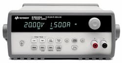
Most laboratory-grade programmable instrumentation power supplies (Fig. 1) have built-in voltmeters and ammeters for measuring the actual voltage and current being sourced by the power supply. If that power supply is powering up the motor, then the motor’s voltage and current will be shown on the power supply’s display.
A voltage-measuring circuit (basically, a dedicated voltmeter) and a current-measuring circuit (basically, a dedicated ammeter) reside within the power supply. But unlike a general-purpose voltmeter or ammeter that sit on the lab bench alongside of the power supply, the supply’s built-in ammeter function has three important capabilities that make it better than that nearby digital multimeter (DMM) for measuring the current flowing from the power supply into the device under test.
First, the built-in ammeter function is sized for the current being supplied by the power supply. A typical DMM, in ammeter mode, is limited to perhaps 10-A maximum current, whereas the built-in ammeter can display the maximum current of the power supply, which could be tens or hundreds of amperes.
Second, the built-in ammeter will not place a “burden voltage” on the circuit being measured. For example, if the motor draws 5 A of current, it is likely that a DMM set to ammeter mode could have a voltage drop across the DMM’s input terminals of 500 mV. This is called the burden voltage; it takes away from the available voltage that can be supplied to the motor because the ammeter’s current-sensing resistance is an additional load in the current path.
The built-in ammeter in the power supply, however, will not exhibit this burden voltage. The power supply continues to provide its programmed output-voltage value, regardless of the current being drawn by the motor. This assumes, of course, that you are using properly sized load wires; the motor current does not exceed the rating of the power supply; and you are using remote sensing on the power supply (for more information about remote sensing, see “Remote Sensing Improves Voltage Sourcing at High Current”).
Third, the built-in ammeter does not require you to break the wiring path between the power supply and the motor being measured. To use an ammeter, you must run the wires between the motor and the power supply into the ammeter. However, the power supply’s built-in ammeter can sense the current from within inside of the power supply, so the wiring between the power supply and the motor is uninterrupted.
Conceptually, to measure dc motor speed using the power supply, you measure the current being drawn by the motor using the power supply’s built-in ammeter function. If that built-in ammeter can show the actual current waveform being drawn by the motor, you can then easily look at the waveform and identify the motor’s rotation and thus calculate the motor speed. Practically speaking, to be able to measure the motor’s speed requires a power supply with high-performance built-in ammeter functions.
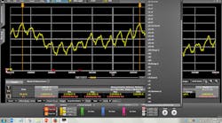
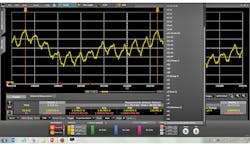
The typical power supply will most likely use an integrating ammeter function, which will take tens of milliseconds (or perhaps even more) to return a single average current measurement value. This means the measurement from the power supply will not be a waveform, but a single value integrated over that long measurement window. Measuring motor speed requires a power supply that can digitize the current waveform at thousands of samples per second. The power supply must be able to display that information on its front panel or return the digitized current information to a PC for analysis (Fig. 2). The results in the figure were capture using Keysight 14585A software.
Advanced power supplies today can digitize current flowing into the motor and return the waveform for visualization and analysis. An example of this capability is found in Keysight’s N7900 Advanced Power System DC Power Supplies (Fig. 3). With up to 200 A of source current and up to 160 V of source voltage, this family offers the high-accuracy current measurement necessary for even large dc motors. When coupled with the Keysight 14585A Control and Analysis Software, it’s easy to view the motor current waveform data and determine motor speed without having to use any extra RPM measurement instrumentation.
This file type includes high resolution graphics and schematics when applicable.


