Analog-Resolution Digital Multimeter Features Audible Accessory
Digital multimeters are precise and accurate instruments, with some models being very expensive. No matter the cost, one problem pervades every one of these devices: They do a poor job of conveying the analog behavior of an input signal.
This file type includes high resolution graphics and schematics when applicable.
To perform an operation where you want to maximize or minimize some parameter when making an adjustment, you must visually monitor the reading closely and really study the numerical display to determine whether the rapidly changing digits are increasing or decreasing, or varying randomly over a small or large range of values. This process requires both your eyes and your concentration, while still attending to the process of performing the adjustment and perhaps holding a test probe steady in the correct position.
Some high-end digital multimeters (DMMs) come with a crude bar graph on the liquid-crystal display to convey analog information. However, these are generally useless and make one yearn for an old analog moving-needle meter.
Instead of a bar graph or a moving needle, my solution produces a sound whose audible frequency (pitch) changes along with the magnitude of the digital display. As the displayed magnitude increases, the audible frequency increases; and as the displayed magnitude decreases, the audible frequency decreases. This turns out to be an incredibly effective way to convey precise analog behavior, as good as or better than watching an analog-meter needle, and you don’t have to watch the display.
Audible-Tone Frequency Represents Magnitude
The human ear is able to resolve small changes in pitch (frequency). This arrangement provides better resolution than an analog-meter needle, and you can look at what you’re probing and adjusting while listening for the resultant parameter changes. This method yields eyes-off measurements. You can maximize, minimize, or make relative changes without looking at the instrument!
For the prototype that I built in 2008, I used an LM331 precision voltage-to-frequency converter (VFC) to produce an audible tone proportional to the voltage across the digital meter within the DMM. The DMM conveniently serves to convert all inputs, whether voltage or current or resistance or any other parameter, to a voltage in the range of ±199.9 mV or sometimes ±399.9 mV, depending on the particular unit.
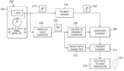
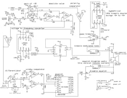
Buffer the signal from the input to the internal digital meter, amplify it, take the absolute value, apply it to the VFC, convert the low duty-cycle pulse output to a high duty-cycle signal, and apply it to a loudspeaker to generate a suitable audible tone. Figure 1 illustrates the concept, while Figure 2 shows the schematic diagram of one successful early prototype.
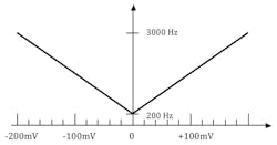
The audible frequency will vary with the magnitude of the voltage to the meter within the DMM (Fig. 3). So far, this circuit performs like an audible bar graph with very high resolution. With an absolute-value converter between the input buffer amplifier and the VFC, it ignores signal polarity. Just like a DMM with an analog bar graph, it gives the same indication for positive and negative inputs.
Representing the magnitude of a measured parameter as audible pitch isn’t a new idea. I used this method of presenting signal values as varying audible frequencies in previous inventions1 and an article in QEX.2 I still have some hardware I used around 1988. It actually has the earphone in a rubber cup from a 300-baud modem to couple the audible output signal into a plain-old-telephone handset to convey measurements over a telephone connection to me at a remote location, where I made adjustments to a free-space optical data link that affected the measurement.
Audible Polarity-Indicating Feature
To make this device more usable, I set out to make positive polarity and negative polarity signals sound different with the polarity sensor and the waveform changer. I initially went between a sine wave and a square wave, but the difference was more pronounced when I used tremolo, a low-frequency amplitude variation, to denote negative signals. The amplitude envelope of the audio pitch varies at low frequency when the input polarity is negative to give negative inputs a very noticeable and distinctive sound.
Squelch Feature
Ray Bosenbecker, my friend and colleague, pointed out how annoying the audible tone became, especially when it wasn’t changing between adjustments. Ray suggested the addition of squelch when the input signal was invariant for a while. At this point, he became a co-inventor.
Naturally, the squelch was the most difficult feature to implement. Four op amps serve to buffer and differentiate the signal at the input of the VFC and sense sudden changes.
When the reading remains invariant for a while, the audible tone ceases. When the reading begins to vary again, the tone resumes. This was touchy and difficult to adjust in the prototype circuit with squelch (Fig. 4). It did function well enough to demonstrate the concept.
I wanted to reduce this circuit to fit within a DMM, but suitable analog equivalents of complex programmable logic devices (CPLDs) and field-programmable gate arrays (FPGAs) never happened. Consequently, I had only this complex and unsuitable analog circuit that was too large to fit and required inconvenient power-supply voltage levels.
Digital Implementation
My friend Lee Johnson encouraged me to attempt a digital version. I resisted for a long time, though, since it seemed silly to digitize the signal both in the DMM and my audio accessory.
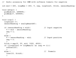
When I finally sat down to try a digital implementation, it proved to be very simple and worked on the first try. The digital prototype breadboard was an Arduino Uno R3 running an example program called “tonePitchFollower,” which is equivalent to a VFC. The circuit still needs op amps to buffer and amplify the input to a range that’s acceptable for the unipolar analog-to-digital converter (ADC) on the Arduino. Matching voltage ranges to frequency ranges, adding tremolo to distinguish negative polarity, and implementing squelch are just software.
The first fully functional digital prototype used an Arduino ProMini and readily fit into the available space within a low-end Cen-Tech DMM from Harbor Freight. The next used a full-size 28-pin Atmel ATmega328P chip from an Arduino Uno R3, and it fit just as well. I recently got the 8-pin Atmel ATtiny85 chip to work as well as the higher performing chips, so there’s now plenty of room, and it requires less current.
Figure 5 shows three generations of prototypes with various Atmel processors. The first is an Arduino Pro Mini, the second is an ATmega328P chip from an Arduino Uno R3, and the third is an ATtiny85. An early version of the simple program for the Arduino Uno demonstrates the method without squelch (Fig. 6).
The Hack
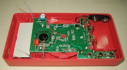
The Harbor Freight DMM takes power from a 9-V battery and delivers a regulated reference potential 3 V below the positive battery potential. The input signal to the internal digital meter varies ±200 mV with respect to this reference potential. I sampled the reference and digital meter input signal on two sides of a chip capacitor using blue and red wires (Fig. 7, lower left). I connected to the switched +9-V power with the red wire near the center and to the –9-V power with the blue wire to the upper right. This power arrangement holds the secret to hacking the Harbor Freight DMM to provide power to the bipolar op amps and the Atmel processor.
Figure 8 shows the DMM voltage levels and the circuit diagram of this audible accessory. The 79L05 negative voltage regulator derives a potential 5 V below the +9-V battery (after the power switch). The op amps and the CPU chip use this as the negative supply and the +9-V battery potential as the positive supply. In this way, the DMM reference and DMM output-signal potentials lie just about midway between, and in a fixed relationship with, the op amp and CPU supplies.
The ATtiny85 version draws less than 14 mA from the battery, including the DMM when operating with a 150-Ω loudspeaker. The loudspeakers come from old cordless telephones. I see them on the Web, but the supplier hasn’t responded to an enquiry.
A Fluke 23 DMM I examined uses the same power-supply configuration as the Cen-Tech DMM from Harbor Freight. I conclude that this hack applies generally, and not just to Cen-Tech models. I recommend starting with Cen-Tech models, because Harbor Freight offers coupon deals that give them away for free from time to time.
Self-Calibration Feature
Lee Johnson suggested that it would be useful to have the audible DMM indicate the approach to particular input-signal levels other than zero for purposes of repetitive calibration in an industrial setting. I added this feature to the software and solved my own calibration problem.
Previously, each unit required a slightly different constant in the software to force the minimum audible frequency to occur exactly when the DMM display indicates zero. Now, if pin 2 of the CPU is low at power-up, the unit will self-calibrate to whatever input level is present and store the calibration constant in the non-volatile EEPROM memory of the CPU. Short the input, pull pin 2 low, and apply power to calibrate the unit normally. I use an internal reed switch and an external magnet to pull pin 2 low without drilling a hole in the case for a switch, but that would work as well.
Offset-Calibration Feature
Apply any positive or negative input level to the unit while measuring any parameter on any range. Turn power off, pull pin 2 low, and reapply power to calibrate the unit to indicate minimum frequency and zero crossings at that specific input level. Depending on your meter, you could do this with capacitance, resistance, and frequency as well as voltage, current, and resistance.
Now you can pay attention to probe placement or the specifics of performing your adjustment while simply listening and adjusting for minimum audible frequency. This is how the instrument indicates whether the input level approaches or departs from the parameter value you desire.
I believe that this offset calibration feature is a new and possibly patentable idea, but Lee and I instead chose to disclose it in this article. You’re welcome. Name it after us.
Other Uses
Test whether a potentiometer is dirty (noisy) or makes good contact throughout its range by setting up to measure resistance and listening for dropouts while you rotate the shaft. They will be very noticeable. You may also gain insight into whether the resistance variation is linear or has a logarithmic taper.
Consider using the accessory board with any ±199.9-mV or ±399.9-mV digital panel meter that you build into your own applications. You will have to change the power arrangement to provide a symmetrical or nearly symmetrical power-supply range of about 5 V that extends both above and below the reference input to your meter. Different meters will require different solutions. Someone should eventually offer digital panels with this functionality built in. This accessory provides a very versatile audible continuity check to digital meters that lack this feature.
This file type includes high resolution graphics and schematics when applicable.
On a unit with the squelch feature, leave the instrument to monitor a critical supply or bias voltage that shouldn’t vary. When it does, the unit breaks squelch to provide an alarm.
Availability
I do not plan to make and sell digital multimeters. However, to popularize my method, I’m considering ways to provide this accessory as a small assembled and operating circuit board that users can build into their own DMMs. These units have sockets for the ATtiny85 CPU, so users can tailor software to their own applications. Figure 9 shows a new printed-circuit board that accommodates a reed switch for self calibration when enabled with an external magnet.
This accessory should become available from Citrus Electronics.3 Check the website for status. If there’s demand for the remaining boards, we will fabricate more of them.
I can provide these accessory boards with software that generates an audible tone whose frequency increases and decreases with the magnitude of the DMM’s numerical display. The Boeing Company owns U.S. patent 8,803,560,4 which covers the audible polarity-indicating feature and the squelch feature, so I cannot provide those (see “Intellectual-Property Patent Restrictions” below).
Imagine what else you can do with this setup. I can think of several improvements, and have already incorporated a couple into the available version. My goal is to see DMMs with these features available to users who have long complained about the lack of decent analog indication. I hope this happens. I even hope Boeing makes some money.
Dr. Sam Green is a retired aerospace engineer who specialized in free space optical and fiber-optic data communications and photonics. He holds degrees in electronic engineering from Northwestern University and the University of Illinois at Urbana. Listed as inventor on 18 patents, he is a Registered Professional Engineer in Missouri and a life senior member of IEEE. Contact Sam at [email protected].
1. See patents 5,729,335 and 7,898,395.
2. “Fun with Voltage-to-Frequency Converters,” QEX, March/April 2013, pp. 7-10.
3. http://www.citrus-electronics.com
4. http://www.google.com.ar/patents/US8803560
Intellectual-Property Patent Restrictions |
|
The use of a voltage-to-frequency converter (VFC) to indicate magnitude changes as proportional changes in audible frequency is not a new concept. The voltage-to-audible-frequency principal is public property by now, because that’s what VFCs do and because I did it so long ago. The addition of tremolo to distinguish between positive and negative polarity is new, though. The use of squelch to silence the tone when it ceases to change and to turn the tone on again when change resumes is another new twist. The Boeing Company holds patent number 8,803,560 that covers these two features. I describe the implementation of this invention here, because I would like to see this method in wide use. Anyone interested in licensing the features of this method in the U.S. must deal with my former employer. Boeing owns the patent on the squelch and tremolo features, so I cannot offer to sell units with tremolo or squelch. I can instead provide the ATtiny85 CPU with alternative software that audibly indicates zero crossings in place of indicating polarity, which proves remarkably effective. You will have to interrupt power to make it quiet or program a fixed operating time until shutoff, rather than sensing when the input ceases to vary or again begins to vary. Note that there is only a U.S. patent. Therefore, anyone can build and sell units with the tremolo and squelch features outside the U.S. I do hope one or two manufacturers will license this method so that they become available here in the United States. Call it the Green Whistler or something cool so I get some credit. |
