Choose the Right Current-Measurement Technique for Your Application
This file type includes high resolution graphics and schematics when applicable.
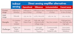
Current-consumption monitoring is more important than ever due to the overwhelming trend toward smaller-sized electronic systems with increased functionality. Picking the correct method to monitor current for a given application is critical in optimizing system performance. The first step in that process is to decide whether to use indirect or direct measurement techniques (see the table).
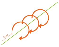
Indirect sensing is based on the Ampere1 and Faraday2 laws. The basic principle is that as current flows, it produces a magnetic field proportional to the current level (Fig. 1). By measuring the magnetic field’s strength and knowing the material properties, you can calculate the value of the load current (ILOAD). The sense elements are typically called either Hall-effect3 or VAC4 sensors. This non-invasive method is inherently isolated from the load.
The measurement system doesn’t cause any loss of power in the load. It can be used for high currents (>100 A), high voltages (>100V), dynamic current loads, and any area that requires isolation. Indirect sensing is typically more expensive due to the magnetic sensors. In addition, indirect sensing has historically required a fairly large footprint to accommodate the magnetics relative to the current flow.
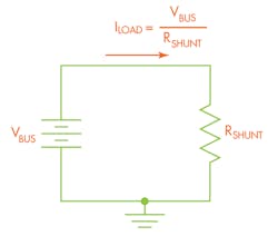
Direct sensing is based on Ohm’s law (Fig. 2). The principle simply states that the current flowing through a resistor is directly proportional to the ratio of the value of the voltage applied to the resistor value. The resistor, known as a shunt resistor, is placed in series with the load, and either the supply or ground. It is an invasive measurement that adds power dissipation into the system. Isolated and non-isolated solutions are available.
Recommended for lower currents (<100 A) and voltage levels (<100 V), direct sensing offers a lower-cost method of current measurement. However, isolation techniques and options can extend into the kilovolt range. The system must be able to tolerate a small power loss in the load.
Direct-Current-Sensing Alternatives
Since direct current sensing is an invasive measurement technique, one key design goal is to minimize the amount of additional load the measurement places on the system. For this to happen, the sense-element shunt resistor must be kept very small. Typically, the shunt resistor value is less than 50 mΩ, and in a number of cases it can fall below 1 mΩ. The small resistor values result in a fairly small voltage drop, even with 100 A. Using such small voltages requires signal conditioning.
A differential amplifier configuration helps amplify the small signal to usable levels. Four primary differential amplifier configurations can be used to measure current:
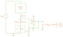
Operational amplifiers (op amps) offer the most basic implementation. They rely on external discrete components to set gain and precision levels. As a result, they’re typically used only in lower-accuracy, cost-sensitive applications. Since they require a feedback path, the input is single-ended and can only really be employed in low-side configurations (more on this shortly). The single-ended nature makes the configuration susceptible to parasitic impedance errors (Fig. 3). Cost savings are offset significantly if high-accuracy external components are used to increase precision.
Difference amplifiers are specialty op amps that integrate gain networks. Thus, they can be used in differential configurations that eliminate parasitic impedance errors. However, the integrated gain networks are designed to convert large differential signals to large single-ended signals, typically with unity gain. As mentioned earlier, the small input-signal level requires higher gains than that offered by a typical difference amplifier. Therefore, the difference amplifier’s architecture doesn’t lend itself to most current-sensing applications. Since they can tolerate very high common-mode voltage ranges on their inputs, the devices can be used as a buffer stage in various applications.
Instrumentation amplifiers are specialty three-stage devices that combine a difference amplifier with two buffers, one on each input. This creates a large input impedance, making it possible to measure very small currents. Such a configuration also eliminates the parasitic impedance error of the single-ended op-amp configuration. However, the architecture limits use to applications in which the common-mode voltage falls within the supply voltage range.
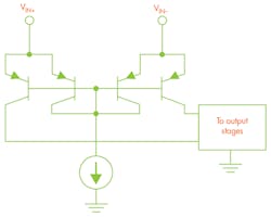
Current-sense amplifiers (also called current-shunt amplifiers or current-shunt monitors) are specialized amplifiers that feature a unique input stage (Fig. 4). Thanks to their topology, the amplifier can be exposed to common-mode voltages that are significantly higher than the supply voltage. In addition, they integrate a high-precision, low-drift gain network that maximizes measurement accuracy. The input structure is such that limits the use cases in which ILOAD is greater than approximately 10 µA.
Deciding on the Current-Sensing Implementation
The answers to several important questions will determine your implementation choice and ultimately help drive device selection:
• Will the measurement be on the high or low side?
• What is the common-mode voltage to be measured?
• What is the current range to be measured?
• Is the current bidirectional or unidirectional?
• How will the current value be used?
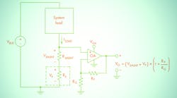
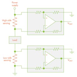
Earlier, I mentioned that op amps are only really good for low-side implementations, and that more was to come. Well, that time is now. A low-side implementation has the shunt resistor placed between the load and system ground (Fig. 5). It’s the most common method to monitor current, since the common-mode voltage is essentially 0 V and tends to allow for lower-cost device selection. However, this disturbs the ground seen by the load, as well as prevents the detection of load shorts-to-ground.
A high-side implementation places the shunt resistor between the supply voltage and the load, resulting in the common-mode voltage essentially being equal to the bus voltage. In many applications, this may be well above the supply rail of the amplifier. High-side sensing allows for good system grounding and ground-short detection.
I discussed that the common-mode voltage level is critical in determining the implementation. When looking at specific devices, you need to ensure that the device’s common-mode voltage range includes the application’s common mode. Clearly, if high-side is chosen, it’s crucial that the device’s maximum common-mode voltage accommodates the actual common-mode voltage being monitored, as well as any additional protection margin required by the application.
As the maximum common-mode range increases, it typically means a reduction in the achievable accuracy. For example, Texas Instruments’ INA210 current-shunt monitor has a maximum common-mode voltage of 26 V and offers an input offset voltage of 35 µV. Input offset is one of the most important device parameters when determining measurement accuracy. Now compare the specifications of the INA210 to those of the INA283 current-sense amplifier. Its common-mode range extends up to +80 V (as well as down to –16 V), with a maximum input offset of 70 µV.
When using a low-side implementation, you need to ensure that your device includes 0 V in the common-mode range. Some older current-shunt monitors such as the INA138 were designed to be high-side only. Its common-mode range is 2.7 to 36 V and, therefore, cannot be used on the low side.
While the current range itself doesn’t derive any amplifier specifications, it becomes critical when deriving overall implementation requirements. The maximum current to be measured combined with the maximum differential input of the amplifier sets the value of the shunt resistor. What follows the amplifier in the signal-conditioning path is a key factor in calculating the shunt value, as well as the gain of the amplifier stage.
For example, if the output voltage is feeding the input of an analog-to-digital converter (ADC), you want the maximum current value to be close to the full-scale input range. The minimum current value combined with the shunt resistor determines the amplifier’s minimum differential-voltage requirement.
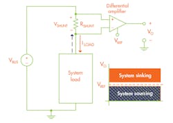
In many applications, current may flow in both directions. For instance, many battery-powered devices allow for charging of the batteries. When charging, the current flows from the load to the supply battery. Conversely, when in use, the current flows from the battery to the load. To determine if the battery is charging or discharging, you need to determine the current-flow direction. However, to accomplish this task, the amplifier must have an additional input pin that can be used to divide the output voltage range into system sinking or sourcing current (Fig. 6).
The next key decision in device selection revolves around the answer to: “How is the current ‘information’ being used?” But perhaps the real question is: “What is the next link in the signal conditioning chain?”
Output type, in other words, analog, digital, or alert, is determined by where the information needs to go and how it’s used. If the current level is utilized purely as feedback/control of another analog device, then sticking with analog output may make the most sense. If the information will be processed by a microcontroller, then using a digital output device, such as the INA226, may make the most sense (it could also save additional signal-processing cost). If the only requirement is a comparison to an overcurrent threshold, than a simple ALERT output, such as the INA300, may be all that’s needed.
Many application requirements can help determine the best current-shunt monitor for any system implementation. This article didn’t address what may be the most important concern—the required accuracy and maximizing that accuracy. Look for a future article addressing accuracy as it deserves its own treatment.
Summary
Many alternatives exist for monitoring current in systems. Choosing the correct method for monitoring current in an application is critical toward optimizing its performance. The application requirements (such as voltage being monitored, current range, how the information will be used, required precision, and so on) will determine the basic configuration to use to implement your current monitoring.
This file type includes high resolution graphics and schematics when applicable.
References:
