5 Things You Didn’t Know RF Signal Generators or Analyzers Could Do
This file type includes high resolution graphics and schematics when applicable.
A decade ago, innovation in the test-and-measurement industry started pushing the capabilities of vector signal generators and analyzers to wider bandwidths, faster tuning times, and greater signal-processing capabilities. Over this time period, these instruments have evolved from a heavily analog device to a highly sophisticated supercomputer, which also happens to have a killer analog front end.
Given this evolution, I thought it would be worth reviewing several of the applications that engineers are solving with modern RF signal generators and analyzers. Although some of these applications were unthinkable a decade ago, advances in instrumentation technology now make them commonplace.
Implement DPD Algorithms
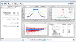
Digital predistortion (DPD) is a common technique used to correct for nonlinear behavior in RF power amplifiers (PAs) (Fig. 1). It involves digitally modifying a waveform at baseband before upconversion to RF. Because the DPD algorithms historically require intense computation and were embedded on an application-specific integrated circuit (ASIC), testing a PA’s performance under DPD conditions required incredibly complex test configurations.
Today, engineers are able to test a PA’s performance under “DPD conditions” using off-the-shelf vector signal generators and analyzers. With this setup, the instruments first extract a model of the PA’s behavior. Then, using the model, the signal generator’s software applies one of several standard DPD algorithms to the baseband waveform. By generating this modified waveform, the signal generator replaces the functionality of the DPD ASIC and allows the engineer to test PA performance under DPD conditions.
Record and Playback Signals to and from Disk
A decade ago, the onboard memory of a vector signal generator or analyzer determined the maximum duration of signal that could be generated or acquired by an instrument. Typical onboard memories ranged from tens to hundreds of megabytes, allowing up to a few seconds of waveform generation or acquisition. For longer waveforms, such as the generation of a GPS signal (which often requires several minutes to be useful), you were simply out of luck.
Over the past decade, the evolution of high-throughput bus technology has revolutionized the way that vector signal generators and analyzers can produce or consume data. During this time, bus technology progressed from the days of GPIB delivering megabytes of data per second to today’s PCI Express implementations that deliver several gigabytes per second. For example, modern PXI modules using x4 (pronounced “by-4”) PCI Express data links are able to stream up to 3.2 GB of data per second from a high-speed hard drive to a PXI module. With complex waveforms consuming 32 bits per sample (16 bits for I, and 16 for Q), 3.2 GB translates to 800 Msamples of IQ waveform per second.
Thanks to modern bus technology, onboard memory size no longer determines the maximum waveform size in a modern RF signal generator or analyzer. Instead, it’s determined by the amount of hard-drive space one can assemble. In fact, today’s engineers can create or acquire waveforms that are literally tens of terabytes in size. The dramatic increase in waveform record sizes has introduced new applications for instrumentation. One of the most common is to record RF spectrum off the air using an antenna and then play it back to a wireless device in the lab.
Measure S-Parameters
Similar to how we’re beginning to see modern vector network analyzers (VNAs) with spectrum measurement capabilities, we’re also seeing vector signal generators and analyzers evolve with S-parameter measurement capabilities. Historically, network analyzers measured S-parameters through a stimulus signal combined with a tightly controlled arrangement of directional couplers and receivers.
Although a high-end traditional VNA is still the preferred method to perform the most accurate S-parameter measurements, it’s not always the most economical. Now, more engineers are adopting a VNA architecture that combines a vector signal generator and analyzer with a “port module,” especially in high-volume production test applications for semiconductor components. The port module provides a series of directional couplers along with signal-conditioning hardware to turn the VSA/VSG into a VNA. The port-module approach typically results in significant cost savings for engineers that are already performing vector or spectrum measurements.
Process Signals in Real Time
April 19, 2015 marked the 50th anniversary of Moore’s law, a simple observation from Gordon E. Moore that transistor density would double every two years. Over the past 50 years, the reliability with which new processor performance has tracked Moore’s prediction has made his observation famous.
The last 50 years of exponential processor performance growth has created a scenario where the modern RF signal generator or analyzer now possesses the computational capabilities of a supercomputer. In fact, it’s worth noting than in 1965, a state-of-the-art IBM 7904 computer was capable of performing 100,000 floating-point operations per second (FLOPS). Today, the iPhone 6 literally has a million times this processing performance, and a modern RF instrument offers tens of million times this performance.
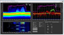
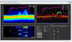
The end result of such immense signal-processing capabilities on today’s RF signal analyzers is the ability to process signals in real time. Not only can today’s advanced RF signal analyzers perform spectrum measurements in real time as part of a real-time spectrum analyzer, they can also execute other signal-processing algorithms as well (Fig. 2). For example, engineers use the LabVIEW-programmable FPGA on PXI RF signal analyzers to implement algorithms such as demodulators, multi-channel DDCs, and more.
Synchronize for MIMO and Multichannel Applications
Another capability of modern RF signal generators and analyzers that’s progressed significantly over the past decade is the ability to synchronize multiple instruments for multichannel applications. Historically, synchronizing multiple signal generators or analyzers was tricky—if not impossible—due to the relatively closed architectures of the instrument. Today, however, many VSGs and VSAs are designed such that multiple instruments can share their internal local oscillators (LOs).
As a result, engineers can synchronize four, eight, or even more RF instruments for phase-coherent signal generation or acquisition applications. With the emergence of multiple-input multiple-output (MIMO) antenna technology in standards such as IEEE 802.11ac and LTE Advanced, the ability to synchronize multiple instruments has become a substantial asset for engineers testing MIMO transceivers. In addition to these applications, engineers are using multi-channel instruments for a wide range of electronic-warfare applications ranging from phased-array radar prototyping to direction finding.
This file type includes high resolution graphics and schematics when applicable.
Conclusion
No doubt, that old signal generator or analyzer in your undergraduate electrical-engineering lab is substantially different than today’s instruments. In fact, the emerging capabilities of these instruments are empowering engineers to use off-the-shelf instruments in an ever-expanding field of applications that were once solved by designing one’s own custom instrument. Thus, if you have a crazy signal-generation or acquisition need, and thought you’d have to design your own hardware, think again. No matter how extreme your need might seem, it just might be possible to solve it with an instrument.


