Why You Should Care About Oscilloscope Acquisition Modes
The movement from analog to digital oscilloscopes has opened up a new world of measurement opportunities for engineers. By using an ADC paired with a plotter instead of a sweep generator paired with a CRT, you can change how your signal is acquired. Extracting the most confidence from your oscilloscope readings requires understanding the strengths and weaknesses of different acquisition modes. Learn how normal, averaging, and high resolution modes work, and when you should use each one.
What are Oscilloscope Acquisition Modes?
Acquisition modes are finely tuned sampling algorithms that give you unique insights into your signal. By varying the sample rate of the scope’s analog-to-digital converter (ADC) and selectively plotting or combining sample points, different characteristics of a signal can be observed. It’s worth noting that sample rate is not the same as bandwidth. Sample rate is how fast the ADC acquires samples. The scope’s bandwidth is a specification that defines the front-end hardware’s ability to capture a signal’s frequency content.
Normal Acquisition Mode
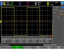
Normal acquisition mode is the default mode for oscilloscopes. The ADC samples and the scope decimates down to the desired number of points and plots the waveform. It’s best to use normal acquisition mode for day-to-day debugging tasks because it gives a good general representation of your signal. It’s a very safe mode to use, and has no significant caveats.
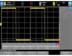
1. A 100-kHz clock signal captured using normal acquisition mode.
Averaging Acquisition Mode
Averaging acquisition mode is probably the second most commonly used mode. Averaging mode takes multiple waveform captures and averages them together. The main benefit of averaging acquisition mode is that it averages out the random noise on your signal; this allows you to see just the underlying signal. For example, clamp-on current probes are notoriously noisy. Therefore, using averaging mode will help give you more insight into what your current waveform actually looks like.
This mode should only be used under certain circumstances or you could get misinformation on the screen. Averaging acquisition mode should be used only with periodic signals and with a stable oscilloscope trigger. If the signal is aperiodic, the displayed signal will not be valid data—just a conglomeration of changing signals over time. If there’s a glitch in the signal, it will be hidden by the continuous averaging.
Debug any suspected glitches in a different mode or use advanced triggering techniques such as zone triggering. If the scope doesn’t have a stable trigger, then the averaged waveforms won’t be properly aligned in time and you will see artifacts similar to that of an aperiodic signal in averaging mode. It’s best to check and make sure that you have a stable trigger in normal mode before switching to averaging mode. You can also use advanced triggering techniques to stabilize your trigger.
Averaging mode is a great acquisition mode for viewing or characterizing very stable periodic waveforms, but it must be used appropriately.
High-Resolution Mode
High-resolution mode is another form of averaging. However, instead of waveform-to-waveform averaging, it is point-to-point averaging. Essentially, the ADC oversamples the signal and averages neighboring points together. This mode uses a real-time boxcar averaging algorithm that helps reduce random noise. It also can yield a higher number of bits of resolution.
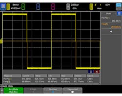
2. A 100-kHz clock signal captured using high-resolution mode.
High-resolution mode isn’t as effective at reducing random noise as the averaging mode discussed earlier, but it has some distinct advantages. Because high-resolution mode doesn’t depend on multiple captures, it can be used with aperiodic signals and unstable triggers. This makes high-resolution mode much better than averaging mode for general-purpose debugging. However, averaging mode does a more complete job of removing random noise from the oscilloscope trace.
A couple of things to be aware of when using high-resolution mode: First, if you zoom out too far (too slow a sweep speed), it’s possible for some of the signal to be averaged out. If the entire period/cycle of a signal falls within the effective sampling period, the entire waveform period/cycle will be averaged together and the resulting plotted point will be zero. So, high-resolution mode should only be used with, at most, a few cycles of your signal on screen. Second, at very fast sweep speeds (time-per-division settings), the sample rate of the ADC will be at its maximum. This means that the scope won’t be able to oversample the signal and will behave as if it’s in normal acquisition mode. Consequently, high-resolution mode won’t add any significant advantages at the fastest settings.
High-resolution mode is a useful mode for maximizing the bits of resolution on the scope. To learn more about how to maximize your bits of resolution, see the article “Make Great Oscilloscope Measurements.”
Peak-Detect Acquisition Mode
Peak-detect acquisition mode functions similar to high-resolution mode. The ADC oversamples the signal and selectively chooses which points to display. But, instead of averaging these points together, peak-detect mode chooses the highest and the lowest points and plots them both. This is useful because it can provide insight into any unusually high or low points that might be otherwise hidden. Peak-detect mode is best used for detecting glitches or viewing very narrow pulses.
Like high-resolution mode, at fast sweep speeds, the ADC won’t be able to oversample the waveform. Therefore, peak-detect mode is best used at moderate sweep speeds. In addition, using peak-detect mode can give a distorted view of the true signal by plotting the highest and lowest points in a given sampling period.
The 100-kHz Clock
Let’s look at an example of how the different acquisition modes perform on an identical signal. Figure 1 shows a 100-kHz, 500-mV, peak-to-peak clock signal captured using normal acquisition mode.
3. A 100-kHz clock signal in averaging mode.
You can see that after almost 11,000 captures, the peak-to-peak voltage measurement averages 508 mV with a standard deviation of 1.22 mV. Visually, the square wave’s trace is a bit thick but about what we expect for this type of signal.
Figure 2 shows the same signal in high-resolution mode. Our average peak-to-peak value is very close to normal mode at 510 mV. Visually, the signal looks very similar to the one we saw in normal mode. What’s very interesting, though, is that our standard deviation on this measurement is now 654 µV—a mere half of what it was in normal mode. High-resolution mode has averaged out some of the random noise spikes and given us a clearer picture of the fundamental clock signal. But it’s blinded us to some potential noise on the signal.
Look at the same signal in averaging mode (Fig. 3), we see a stark difference. Our average peak-to-peak voltage is now 499.8 mV; it’s close to the actual 500 mV of the signal. Visually, we can see that the trace is much thinner. We can infer, then, that nearly all of the random noise has been averaged to zero. Note that the standard deviation has dropped to a minuscule 214 µV, a sixth of what it was in normal mode. This mode is helpful because we can see that our clock is consistently performing over time. However, we must also be cautious, since there’s noise on the signal that we can’t see in averaging mode.
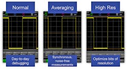
4. A side-by-side comparison of different acquisition modes and their uses.
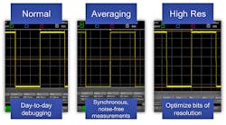
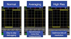
Knowing how different acquisition modes operate is important for using your oscilloscope to its full potential (Fig. 4). Understanding the tradeoffs and choosing the correct mode can make the debugging and characterization of your system much more effective. Averaging mode is helpful for removing random noise on synchronous, stable signals. High-resolution mode is useful for maximizing your bits of resolution while debugging synchronous or asynchronous signals. And, normal mode is ideal for day-to-day debugging. When working on your scope, think about which acquisition mode is best for your signal.
