7 Tips for Better Oscilloscope Probe Selection and Usage
This file type includes high resolution graphics and schematics when applicable.
When considering the right measurement tools for oscilloscope applications, probes are often an afterthought. Many users select the oscilloscope first based on the bandwidth, sample-rate, and channel-count needs, and then worry about how to get the signal into the scope later.
However, selecting the right probe for your application, and how you use the probe, are critical steps toward reliable scope measurements. Below are some of the common considerations associated with selecting probes, and some tips on how to get the most from your probe—and oscilloscope.
1. Passive or active probe
When you buy a low- to mid-range oscilloscope, it usually comes standard with a high-impedance passive probe per oscilloscope channel. Compared to active probes, passive probes are more rugged and less expensive. They offer a wide dynamic range and bandwidth as high as 500 MHz, or more when terminated into the oscilloscope’s 1-MΩ input.
You should consider standard passive probes as general-purpose tools that are designed to perform a broad range of probing tasks. However, a situation may arise in which you need a probe other than the standard passive probe.
For example, when measuring high-speed signals with fast rise/fall time, it’s always recommended to use active probes with sufficient bandwidth. Measuring differential or current signals is best performed with active differential or current probes as well. Therefore, consider a special-purpose or active probe that can do a small range of things better, and ensure best results through proper usage.
2: Single-ended, differential, or multimode
Oscilloscopes measure signals relative to a common reference point, which is ground. The signal measured with an oscilloscope and standard, single-ended probe is the difference in electrical potential between the specific point in the device under test (DUT) and ground.
If you need to measure the voltage across different components in a circuit where one or more of these components aren’t connected to ground, you must make differential measurements. This requires a differential probe in which a differential amplifier amplifies the signal difference between two probing points. It rejects any voltage common to both and then delivers the voltage difference between two points to the input of the oscilloscope.
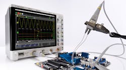
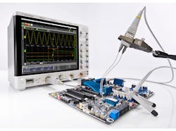
Differential probes are common tools for users of high-bandwidth oscilloscopes, but they can’t easily indicate the individual components that make up differential signals. There’s a growing need in high-speed data signaling for oscilloscope probes to measure the single-ended or common-mode components of differential signals. Newer multimode oscilloscope probes offer multiple modes that can measure single-ended, differential, and common-mode characteristics of a differential signal with a single connection (Fig. 1).
3. Bandwidth
Oscilloscope and probe bandwidth are defined as the frequency response where the amplitude has decreased by 3 dB. Most oscilloscopes or probes with a bandwidth specification of 1 GHz and below typically have what’s called a Gaussian response—a slow roll-off characteristic beginning at approximately one third the –3-dB frequency. Oscilloscopes with a bandwidth spec greater than 1 GHz typically have a maximally flat frequency, or brick wall response, with a shaper roll-off characteristic near the –3-dB point.
For example, if you’re delivering a sine wave that’s equal to the bandwidth frequency into the probe, the –3-dB bandwidth for the probe that you get out of a 1-VP-P sine wave is about 0.7 VP-P at the output of the probe. So, at the –3-dB point, there’s approximately a 30% error in the amplitude measurement of that sine wave.
The rule of thumb is the probe (or oscilloscope) bandwidth should be greater than or equal to 3X to 5X the fastest signal bandwidth on your system. This will avoid attenuating any of the signal’s frequency components.
Therefore, you must first determine the fastest rise or fall time of your particular signal, and derive the signal bandwidth out of it. If you’re working with a particular communication standard, you should be able to find what that standard specifies for fastest rise/fall time. After identifying the fastest rise/fall time, use the following formula to determine the bandwidth of the signal, depending on your thresholds:
For 10% to 90% measurement,
Gaussian bandwidth × TR = 0.35
Brick-wall bandwidth × TR = 0.4
Remember, it’s not the clock frequency that determines the signal bandwidth; it’s the rise or fall time. And, more often than not, probe accessories greatly affect the overall bandwidth, so that should also be considered when optimizing the probe’s bandwidth.
4. Probe loading
Any time you connect a scope probe to a circuit, the probe becomes part of the circuit under test, introducing resistive, capacitive, and inductive loading to the DUT. These electrical characteristics affect the overall measurement system’s response and DUT operation.
Among these three sources of probe loading, capacitive loading is often the most troublesome—it affects bandwidth and rise or fall times, and introduces signal delays. As a result, capacitive loading often alters the shape of the measured waveform.
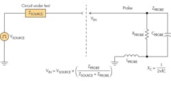
It’s useful at this point to look at a diagram of the DUT with a simplified electrical model of a probe connected to the DUT (Fig. 2). Ideally, the VIN (voltage at the input of the probe) should be the same as the VSOURCE (voltage at the DUT before it’s probed). In reality, since the probe is connected to the DUT, the impedance of DUT and probe determines the voltage at the input of the probe. It’s a simple resistor-divider circuit.
As shown in the figure, at dc, the resistance of the probe determines the loading characteristics, while the capacitive reactance of the probe doesn’t affect the measurement since the capacitive reactance (XC) is infinite at dc. However, as the frequency goes up, the capacitive reactance shrinks and becomes the major source of loading, drawing more and more energy from the DUT.
Modern high-bandwidth probes employ digital-signal-processing (DSP) correction techniques to ensure flat-frequency-response characteristics. However, probe-loading characteristics are determined physically and still affect the DUT’s operation. Most manufacturers specify the input resistance and capacitance value of the probe to give an indication of the loading characteristics.
An oscilloscope’s probe-correction filter can tweak the frequency response to make the waveform look flatter on the oscilloscope screen. However, even with probe correction, you can’t avoid actual probe loading affecting the measurement performance to some degree—we simply cannot defy the laws of physics.
5. Probe noise
Many customers are concerned about the contribution of the probe/scope’s inherent noise to the measurement. Multiple factors contribute to this noise, typically quantified as the signal-to-noise ratio (SNR). Usually, the lower attenuation ratio of the probe leads to a higher SNR with less noise. However, at the same time, it yields a lower input resistance, lower dynamic range, and lower common-mode range, etc.
There are some tradeoffs here. One easy way to estimate the amount of probe noise is to check the attenuation ratio and noise level of the probe specified from the probe’s datasheet or manual.
One aspect to note in understanding the probe-noise characteristics is that the usual characteristic for the probe noise specified by oscilloscope probe manufacturers is its ein (equivalent input noise). Some manufacturers typically quote this quantity as “X mVRMS” of equivalent input noise. For others, it’s quoted as “nV/√Hz” of noise spectrum.
You can convert from one quantity to the other by factoring in the bandwidth of the probe, or using this formula: noise spectrum = ein/√(bandwidth). Both of these are probe-only noise characteristics, referenced to the input of the probe, which may be somewhat different from what’s displayed on the scope.
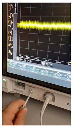
It’s always good practice to characterize the baseline noise generated by the measurement system, which consists of oscilloscope and probe, and verify that the tools used are appropriate for the task at hand (Fig. 3).
To do this, first set up the oscilloscope and probe, as they will be used in terms of V/div, timebase, and connection accessories. Then, short the input and measure the baseline noise. If the measured value of the baseline noise is higher than the noise floor of what you’re looking for, you may want to find another measurement solution that meets your needs.
6. Probe-tip accessories
A measurement system is only as good as its weakest link. The bandwidth of an oscilloscope or probe is always a key banner specification, but the measurement system is more than just the oscilloscope and the probe.
In fact, the oscilloscope is often “not” the weakest link in the measurement system. A measurement system also consists of probes, cables, connectors, and fixtures. Each of these elements has the potential to cause more loss of bandwidth than the oscilloscope. While cables and connectors typically have very low loss, this isn’t the case for probes and probe accessories.
If you see a high-bandwidth probe with clearly longer input lead wires at the tip than similar probes, you can suspect there might be some frequency response variation and degradation. In general, the longer the input wires or leads of a probe tip, the more it may decrease the bandwidth, increase the loading, cause non-flat frequency response, and result in more variation in response as the span and tip wire environment changes. As the bandwidth of the system goes above 1 GHz, the probe-tip effect may play an even more important role in determining the system performance. A very significant amount of probe variation can occur at the probe tip.
If at all possible, keep both the input leads of the probe tip as well as the loop area of connection as small as possible. And, if using a single-ended probe, keep the low-inductance ground connection short and fat.
7. Probe response correction
For a high-bandwidth active probe, probe response correction has become increasingly common. The most common correction method for probes is dc adjustment, which entails the adjustment of the probe’s dc gain and offset. This method has been used for a broad range of passive and active probes to properly compensate for dc gain and offset coefficients.
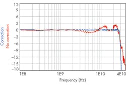
As oscilloscope performance increases to multi-gigahertz levels, the use of a dc correction method becomes insufficient to characterize and correct for the high-frequency response. Instead, ac correction is required. This refers to correction schemes that vary with frequency and attempt to adjust a probe’s ac response characteristics to be in line of an ideal probe that has a flat frequency response up to its rated bandwidth (–3-dB point).
When developing probes, probe-head accessories, and oscilloscopes, the manufacturer measures the S parameters of multiple devices accurately, averages their characteristics, and creates a correction filter that represents the average probe and oscilloscope system (Fig. 4). This form of correction leads to significantly increased accuracy over a nominal correction, without imposing any additional inconvenience upon the user.
However, there’s one important factor you want to keep in mind with regard to probe correction: Probe-correction methods correct for the standard configuration of the probe and probe-tip accessories as offered by the manufacturer. Some oscilloscope users build their own custom probe tips, or modify the one from the manufacturer. The changes in probe tip can drastically change a probe’s behavior and are impossible to capture and correct for using factory correction.
Advanced technology has enabled the development of probe systems with higher performance and more choices for users. If a probe isn’t designed to properly connect with good signal integrity, then all of the expensive equipment downstream of the probe tip can't make up for it.
Looking for parts? Go to SourceESB.
This file type includes high resolution graphics and schematics when applicable.
