This file type includes high resolution graphics and schematics when applicable.
The bit error ratio (BER) is defined as the probability that a bit is received in error when, between transmission and reception, one or more bits are changed (e.g., a binary 0 is transmitted and a binary 1 is received). This measured ratio is affected by many factors, including noise, interference, distortion, attenuation, and jitter. Depending on the telecommunication protocol, BER requirements might vary from 1x10⁻⁶ to 1x10-12.
With the move to higher data rates, bit-error-rate testing will adopt new multilevel-signal transmissions techniques for better performance, such as PAM-4. It will coexist with currently active techniques like non-return-to-zero (NRZ). Let’s take a closer look at the principles behind BER testers (BERTs) and the challenges that the key players in the market are facing—along with the products they are offering to cover the need for data transmission using different forms of signal modulation.
BER Test
BERTs are electronic systems used to detect the BER over any communication link (fiber-optic, Ethernet, radio communication, etc.). A BERT typically consists of a test pattern generator and a receiver to test that pattern. The pattern generator sends a bit stream (stimulus) to the device under test (DUT), which then responds back with another bit stream. The receiver compares the actual response from the DUT with the expected response, which is provided by the user.
A test pattern is usually chosen to emulate the type of data expected to occur during normal operation, but it is also chosen to verify a receiver’s tolerance margins. The most common types of BERT patterns are:
Pseudorandom binary sequence (PRBS): This binary sequence pseudo-randomly generates a stream of repeated or alternating bits. PRBS is difficult to predict. It can be generated using linear feedback shift registers, where the most common used linear function of single bits is an exclusive OR (XOR). The PAM-4 version of PRBS is referred to as a quaternary PRBS (QPRBS) pattern.
Quasi-random signal source (QRSS): This pseudorandom binary sequence is based on a combination of a 20-bit word. It repeats every 1,048,575 bits and suppresses consecutive zeros to no more than 14.
The quality of the BER estimation increases as the number of transmitted bits approaches infinity. But in practice, how many bits do we need to transmit in order to achieve a practical BER performance close to an infinite BER performance? How long does that test take?
The concept of BER confidence level can help answer these questions because, in most cases, we only need to test that the BER is less than a predefined threshold. The confidence level is the percentage of tests that the system’s true BER is less than the specified BER.
“The confidence level is an important factor when doing bit-error-ratio measurements,” explains Ellen Spindler, product manager for BERTs at Keysight Technologies’ Digital & Photonic Test Division. “Typically, digital communication links have to achieve a target BER of less than 10-12. If you just compare 1012 bits with no error, the achieved confidence level is just 63.21%, which is mostly insufficient.
“If you want to achieve a higher confidence level of 95%, for example, you need to compare at least 2.996 x 1012 bits without a single error. The BER test time is directly related to the desired confidence level.”
Mathematically, the confidence level can be expressed as:
CL = PROB [BERT < R] given E and N
where:
CL = BER confidence level
PROB [ ] = “Probability that”
BERT = True BER
R= Specified ratio
Confidence level is a probability whose values vary between 0 and 100%. Once the BER confidence level has been calculated, we may say that we have a CL percent confidence that the true BER is less than R. The quality of the estimate improves as the test time increases. This quality can be quantified using statistical confidence level methods.
Test Challenges
NRZ is a digital data transmission that has been used for several decades. With higher data rates of 400 Gb/s, however, it is better to use other digital data-transmission methods, such as pulse amplitude modulation (PAM-N). Such methods might perform better at such a high rate regardless of the challenges that come with it. IEEE 802.3bs has declared that 400-Gb/s links will use eight 56-Gb/s channels and will allow for the use of either 56-Gb/s NRZ or 28-Gb/s PAM-4.
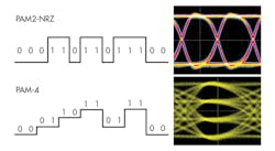
An eye diagram is a common indicator of the quality of signals in high-speed digital transmissions. An NRZ eye diagram contains a single eye, while a PAM-4 eye diagram contains three vertical eyes (Fig. 1). When using PAM-4, there is a tradeoff bandwidth for signal-to-noise-ratio (SNR); the smaller the vertical eye opening (differential amplitude), the more difficult it becomes to maintain a SNR that allows us to interpret the signal at the receiving end of the link.
Some of the challenges are:
Clock recovery: It identifies the crossover point, or the place at which a signal crosses the threshold; however, multilevel signals have both symmetric and asymmetric zero crossings, resulting in a complicated task.
Noise: There are three vertical eyes in a PAM-4 system, and each of them is independently affected by noise; therefore, there is only 33% of amplitude due to level spacing. Due to different rise and fall times between crossings, inter-symbol interference (ISI) can be more significant.
Linearity: PAM-4’s three eye diagrams present a challenge, as each eye should contribute equally to the BER. In other words, the amplitude levels must be evenly spaced, with maximum opening of the three eyes.
Equalization: PAM-4 systems can use equalization to open closed eye diagrams caused by ISI. Channel loss requires enhanced equalization techniques to identify symbols at the receiver or transmitter using techniques such as continuous-time linear equalization (CTLE) and decision feedback equalization (DFE) to correct.
Current options in the market include:
1. Keysight Technologies' M8040A high-performance BERT
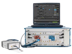
This modular solution can be used to test both PAM-4 and NRZ devices that operate up to 64 Gbaud. The M8040A (Fig. 2) can be used for receiver (input) testing for many popular interconnect standards that implement PAM-4 and NRZ data formats, such as 400 GbE; 50/100/200 GbE; OIF CEI-56G and CEI-112G; 64G/112G Fibre Channel; Infiniband-HDR; and proprietary interfaces for chip-to-chip, chip-to-module, backplanes, repeaters, and active optical cables.
The M8040A is controlled via the M8070A system software, which can be used to control digital applications where non-NRZ data formats are required, such as PAM. The analyzer module provides true PAM-4 error analysis in real-time for long PRBS and QPRBS patterns. In addition, “the remote head concept allows short connections to the device under test, which is beneficial for data-center testing,” says Spindler.
2. Anritsu’s MP1800A Signal Quality Analyzers
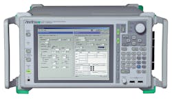
The MP1800A (Fig. 3) is an expandable plug-in modular BERT with built-in pulse pattern generator (PPG). It supports the output of high-quality, high-amplitude signals. In addition, an error detector (ED) with high input sensitivity supports signal analysis, such as bathtub jitter and eye-diagram measurements. The BERT also includes a jitter-modulation source for generating various jitters, such as SJ/RJ/BUJ/SSC, and supporting jitter-tolerance tests.
It can be configured to generate the high-quality, low-S/N, PAM-4 and PAM-8 data signals required for the characterization of high-speed backplanes and 400-GbE interfaces using the PAM-4/PAM-8 Converter (MZ1834A/MZ1838A). The bit error rates of three PAM-4 eye patterns can be measured simultaneously. The MP1800A performs BER measurements of PAM-4 signals using the long-memory programmable pattern function and error-mask function for filtering out unwanted errors. It offers data patterns for various applications—e.g., PAM-4 PRBS.
Additional modules, the MP1861A multiplexer and MP1862A demultiplexer, can be added to the MP1800A. When used in conjunction with the MP1800A, the two modules support a generation of NRZ data and BER measurements at data rates up to 64.2 Gb/s.
3. SHF’s 12104 A and SHF 11104
The bit pattern generators (BPGs) and error analyzers (EAs) from SHF Communication Technologies AG (SHF 12104 A and SHF 11104 A, respectively) deliver a speed of more than 60 Gb/s per channel. The BPGs and EAs are available in two formats: plug-in and benchtop. The BPG generates digital bit sequences, such as standard PRBS or user-defined bit patterns. The 60/64-Gb/s outputs/inputs can operate at both full clock and half clock; for example, a 20- or 40-GHz signal is required for 40-Gb/s operation. The BPG is controlled by the intuitive graphical-user-interface BERT Control Center (BCC). The EA can be used with multilevel applications—e.g., 100GbE (using 2x 28 Gbaud PAM-4) and 400 GbE (using 8x 28 Gbaud PAM-4).
Conclusions
The bit error ratio is a vital figure of merit in the digital communication world. 400G Ethernet will play a key role across digital data applications, especially in applications where PAM-4 and NRZ will need to coexist. Hence, considerations for new designs and tests are essential to verify PAM-4 compliance and guarantee interoperability.
References
“PAM4 signaling in high speed serial technology: Test, analysis, and debug” by Tektronix
“PAM-4 design challenges and the implication test” by Keysight Technologies
“Physical Layer Performance: Testing the Bit Error Ratio (BER)” by Maxim Integrated
This file type includes high resolution graphics and schematics when applicable.


