Leverage Smart Test Techniques to Extend IoT Battery Life
Download this article in PDF format.
Reducing power consumption and optimizing power-management functions are primary concerns for Internet of Things (IoT) developers, but the challenges can be quite varied. In the case of wearables, a design goal might be to extend battery life from a few days to weeks. For sensor nodes that could be in difficult-to-access locations, the goal might be to achieve battery life that can be measured in decades.
Regardless of the ultimate design goal, test and measurement plays a critical role in determining if design changes or component selections are extending battery life or making things worse. Although IoT devices benefit from steadily improving components that can operate with very low power levels, accurately describing the power consumption of each component, as well as overall operation on a system level, is essential to making the most out of available energy.
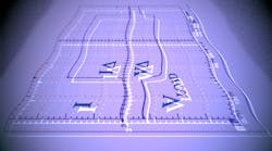
A typical IoT device contains at least one sensor, a processor, and a radio chip that operates in different states and consumes currents from hundreds of nanoamperes to hundreds of milliamperes in a matter of tens of microseconds (Fig. 1). Characterizing low-power-consumption devices to ensure that you stay within a given power budget isn’t a trivial matter. Challenges can include accurately capturing a wide dynamic range of current, capturing complex and fast transmit-mode current waveforms over time, ensuring stable and accurate power to the device under test, and more.
Wide Current Range
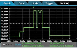
For IoT applications, a device must be able to operate efficiently across operating states ranging from deep sleep, to light usage, to full-on multitasking and intense number crunching. With the number of modes associated with different states of operation, current consumption will jump from hundreds of nanoamps to hundreds of milliamps in a heartbeat.
While conventional instruments may meet either the low end, such as a picoammeter, or the high end, such as a current probe, they typically will not address the full current spectrum. Reconfiguring instrument settings or even test setups is both error-prone and impractical.
For most IoT applications, the best approach to handling this wide dynamic range is to use the auto-range function of a digital multimeter (DMM). Ideally, you’ll want a single configuration setup that can capture a wide dynamic measurement range of voltage and current (Fig. 2).
Deep-Sleep Current
In many IoT applications, devices or sensor nodes can sit idle for hours, days, or even weeks in between periods of peak activity. Depending on the usage model, reducing sleep-mode power consumption can significantly extend overall battery life.
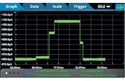
New developments in low-power components and in power management have led to a range of low-power sleep modes that provide finer levels of granularity beyond just run or idle modes, as well as more sophisticated strategies for limiting power consumption. These modes, such as standby, doze, sleep, and deep sleep feature current levels that often range from tens of microamps to as low as tens of nanoamps. Figure 3 shows an example of a multilevel idle-mode current pulse waveform captured in the 100-μA range using a digital multimeter with an 18-bit sampling analog-to-digital converter (ADC).
Some current-measuring techniques—e.g., using a scope with a current probe—fail to achieve the required sensitivity at ultra-low current levels. When using an ammeter, low-current measurement accuracy can be impacted by error sources such as a burden voltage from the internal series resistance that can be as high as 500 mV, as well as error currents generated by triboelectric or piezoelectric effects.
In a shunt ammeter or in a general-purpose DMM, selecting a smaller shunt resistor value reduces the input time constant and results in faster instrument response time. However, this degrades the signal-to-noise ratio, impacting the accuracy and sensitivity of the measurement.
A more suitable option is a specialized DMM with high resolution, such as 7½ digits, with high sensitivity to detect nanoamps and smaller changes, and using low-voltage-burden, feedback ammeter measurement technology. Also valuable for characterizing sleep-mode power consumption is the use of a DMM with a large reading buffer that can store millions of time-stamped readings. This allows you to view device or sensor-node operation over an extended time over multiple active and idle events.
Capturing Short Transients, Fast Transitions
An active IoT device’s operation often consists of states that are short and sporadic yet complex with multiple modes of operation involved. For example, when a device wakes from sleep to active mode, it often takes microseconds to transition from sleep to standby before entering the active mode, and the waking-up process can be difficult to capture using conventional ammeters.
Most ammeters or basic DMMs are dc instruments with slow reading rates. Although many DMMs specify number of power-line cycles (NPLC) to indicate the window in which the data is captured, this specification doesn’t include data-processing overhead. The overall time dictates the instrument’s readiness for the next reading and fast transients can be lost to processing overhead.
Sample rate plays an important role in determining how much waveform detail an instrument can capture. The faster sample rates lead to better reconstruction of the original waveform under test. Per the Nyquist or Sampling Theorem, a signal must be sampled at least twice as fast as its highest-frequency component to accurately reconstruct it and avoid aliasing (undersampling).
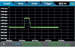
However, Nyquist is just the minimum—it applies only to sine waves and assumes a continuous signal. For fast transient events in IoT device operation, twice the rate of the highest-frequency component isn’t enough. Some DMMs specify a sample rate of 50 ksamples/s. But, at 50 ksamples/s, or 20 µs per sample, small transients that only last tens of microseconds can be missed. Therefore, for IoT applications, it’s advisable to look for a high-speed sampling DMM that can sample both voltage and current at 1 Msamples/s (Fig. 4).
Triggering to Isolate Specific Events
Depending on the application, IoT device operation can involve extremely short bursts of events over a long interval, or a complex state operation that includes multiple events. To analyze these details, triggering is required to scrutinize specific parts of complex and extended waveform.
Conventional current measuring instruments can lack the capability to isolate specific details. For more-sophisticated IoT applications, waveform-oriented edge or level triggers may be inadequate due to such problems as trigger accuracy, trigger latency, trigger skew, and jitter. Low-level waveforms at the microamp range or lower can significantly impact trigger accuracy, depending on the trigger acquisition implementation in the instrument.
Often, the signal and the trigger acquisition are on different paths. Trigger accuracy relies on the sensitivity of the trigger acquisition and can lead to faulty triggering if the instrument can’t react precisely to the trigger event. Trigger latency is an inherent delay between the time the trigger event has been sensed and the start of signal acquisition. Long trigger latency can cause an incorrect indication of when the trigger event occurred, resulting in the required signal not being completely captured.
For more challenging waveforms, advanced triggering options like pulse width, logic trigger, A-B sequence trigger, and synchronous external trigger are helpful. Specialized triggers can respond to specific conditions and make elusive events easier to detect.
Extended Time Recording
As mentioned earlier, monitoring device operation for power-consumption testing over an extended period can be helpful in characterizing system operation. You may need the instrument to log current over a few seconds, a few hours, or even days. Most general-purpose DMMs aren’t equipped with enough internal data storage, and some specialized voltage- and current-measuring instruments that can store up 256k readings will reach capacity very quickly at higher sample rates.
Oscilloscopes are designed to examine extremely short and extremely complex activities by sampling at hundreds of megasamples per second to several gigasamples per second. Due to the complexity of some waveforms and the extremely high number of samples a scope can take, scopes may not be ideal for trending power data over time. A better choice for this type of analysis is a DMM equipped with a large internal data buffer, ideally one that also offers support for real-time data streaming to an external device or computer.
Complex Waveforms Analysis
Power management is at the center of IoT design, but in-depth analysis can be complex, error-prone, and time-consuming. One way to save time is with instruments that can automatically evaluate a waveform based on design requirements.
This type of analysis is where conventional instruments tend to reach their limits. Many ammeters can only acquire current readings. Many DMMs store only a set of current or voltage readings. Some specialized instruments may provide basic statistics such as minimum, maximum, and average. Current probing used with an oscilloscope represents a step forward, along with more sophisticated numerical calculation tools such as RMS calculations, duty cycle, and other math operations.
To accommodate the rapid and varying nature of a waveform, instruments with a graphical display are beneficial for capturing IoT device operation and provide the opportunity to immediately “see” device operation. You will obtain quicker and deeper insight into the operation of your IoT device with advanced features such as measurement “gating,” allowing you to constrain measurements to the screen area or cursors that enable additional control.
Along with an oscilloscope and current probe, the latest graphical sampling DMMs are solid choices for these types of applications. Such instruments can simultaneously capture and display device operation and perform automated calculations on complex waveforms, reducing the time to answer. Look for an instrument with an intuitive and responsive interface that reacts quickly to changing events.
Supplying Voltage
Many low-power IoT devices operate on batteries that are typically in the 3- to 4-V range. At some point in the battery’s discharge cycle, the device will turn off due to the battery’s insufficient output voltage to power the device. To maximize the product’s operating life, it’s important for this low voltage, turn-off threshold to be accurately characterized. Since devices operate over a narrow voltage range, the source used to power the device needs to have good accuracy. This is especially true for the low-voltage turn-off threshold.
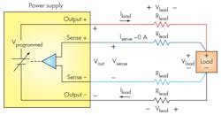
Using a power supply that has remote sensing will ensure that the desired voltage is accurately applied to the load (Fig. 5). No matter how accurate your power-supply output is, it can’t guarantee that the programmed voltage will equal the voltage at the terminals of the device under test (DUT) without the use of remote sensing. A power supply regulates its voltage at its output terminals. However, the voltage you want regulated is at the DUT’s power inputs. The power supply and the load are separated by lead wires that have a resistance, Rlead. The voltage at the load is:
Vload = Vout – 2 × Vlead = Vout – 2 × Iload × Rlead
The remote-sensing technique uses sense lines to automatically compensate for the voltage drop in the leads by extending the power-supply feedback loop to the load. The voltage at the load is fed back to the power supply by the sense leads and ensures that Vload = Vprogrammed.
Also, note that since IoT devices operate at low voltage, it’s important that the source used to power and test the device doesn’t negatively affect the device. Noise from a low-quality power supply can be a potentially significant portion of the 3 to 4 V applied to the device.
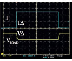
Another problem for power supplies is fast IoT device transitions. As a device transitions from sleep mode or standby mode to a transmitting mode, the load current can change from milliamps to amps—a 1,000% load change in microseconds. Such a fast, large load change can create a problem for a power supply at several levels:
• While the error-correction circuitry is detecting the new load current and adjusting the supply to maintain the programmed output voltage, the voltage is dropping.
• Incorrect measurements on the device can be made when the voltage is low.
• If the voltage drops below the device’s low battery turn-off threshold, and remains below that threshold level long enough for the device to detect the low level, the device will turn off.
To avoid these problems, look for a power supply with a fast response to load changes, ideally below 100 µs, for stable output even during quick mode transitions. Pay close attention to spec sheets in this scenario—transient response is typically defined as the time for the power supply to recover to close to its original voltage when the load changes by 50%. This definition was developed well before the advent of wireless IoT products with much more significant load changes.
Battery Output
One way to assess battery life is to use an actual battery to test the IoT device and determine the amount of time the device remains powered. However, waiting for a battery to discharge can be time-consuming and delay development work. Moreover, such a test method isn’t precise, and specific test conditions are difficult to replicate.
A more effective approach is to use a power source that simulates a battery. This enables testing of a design under a wide range of conditions, from full battery charge to near complete discharge. You can also simulate different types of batteries to determine the best fit for your device. When evaluating battery simulation functionality, look for the ability both to model a battery dynamically over its entire discharge cycle, and to simulate the internal resistance of a battery and minimal voltage drop (fast transient response) to near instantaneous load changes (Fig. 6).
Get Testing
There’s no question that IoT designers are facing a battery squeeze and must overcome the challenges involved with characterizing low-power devices. They must be able to analyze sleep-mode current down to 10-9 A, trigger on short-duration, fast-rise-time waveforms, and capture data over extended periods. And clean, stable, and accurate power to the DUT is a must. With the right tools and techniques, all of these challenges can be overcome and every last drop of available power can be put to good use.
Robert Green is a Senior Market Development Manager for the Keithley Instruments Product Line at Tektronix, focusing on general-purpose and specialized power-supply instrumentation. During his 20-plus-year career at Keithley, Bob has been involved in the definition and introduction of a wide range of products, including picoammeters, electrometers, digital multimeters, temperature measurement products, and power supplies. He received a B.S. in electrical engineering from Cornell University and an M. S. in Electrical Engineering from Washington University, St. Louis, Missouri.
