Cost-Effective Unit Testing and Integration in Accordance with ISO 26262
Download the PDF of this article.
The modern automobile is a maze of interactive electromechanical systems. Many of them, such as brakes, steering, airbags, powertrain, and adaptive driver assistance systems, are critical to human life and safety. Others—such as entertainment systems—not so much. However, they all rely on an exploding volume of software, and in many designs these component systems also share the same internal communication infrastructure. That means that functional safety from a systems perspective as well as at the independent unit level must be assured during the development and testing of this code.
The Purpose and Scope of ISO 26262
ISO 26262 is a functional safety standard for road vehicles that defines requirements and processes to assure safety along a range of hazard classification levels called Automotive Safety Integrity Levels (ASIL). These specify functional safety measures for levels A (least hazardous) to D (most hazardous). ISO 26262 specifies a process that begins with general requirements, the specification of actual safety requirements, the design of the software architecture, and the actual coding and implementation of the functional units. There are also steps for testing and verification of each of these.
The necessary and detailed work of specifying system design requirements and safety requirements can be done at a fairly abstract level using spreadsheets, word processing tools, and more formal requirements-management tools. However, these requirements must also flow down to both the individual software components that implement them and the verification activities that prove them. Under ISO 26262, bi-directional traceability is critical to ensure a transparent and open lifecycle of development. Similarly, if code needs to be rewritten it is important to understand from which upstream requirement it was derived.
Software Architecture Design and Testability
Design-for-testability is often an overloaded term, but the concept is clear under ISO 26262. The software architectural design, called out in Section 7 of the standard, specifically sets out to produce a software architecture that meets the software safety requirements. Modeling tools are often used during this early phase to explore the solution space for the software architecture. Some companies still rely on manual methods of high-level design, using documents or even high-level coding (that is, minus the detailed behavior). Regardless of the method, during design as well as during implementation, the architectural design must be verified. For lower levels of safety integrity, i.e., levels A and B, techniques such as informal walkthroughs and inspections may suffice. For higher safety-integrity levels such as C and D, automation techniques allow developers to cost-effectively perform architectural analysis and review, including in-depth control flow and data-flow analysis. Ultimately, under ISO 26262 the architectural design should lead to a well-defined software architecture that is testable and easily traceable back to its functional safety requirements.
ISO 26262 also requires a hierarchical structure of software components for all safety-integrity levels. From a quality perspective, the standard includes example guidelines such as:
Software components should be restricted in size and loosely coupled with other components.
- All variables need to be initialized.
- There should be no global variables or their usage must be justified.
- There should be no implicit type conversions, unconditional jumps, or hidden data or control flows.
- Dynamic objects or variables need to be checked if used at all.
Without automation, the process of checking all these rules and recommendations against the unit under implementation would be painstaking, costly, and error-prone.
Coding Standards and Guidelines in the Context of ISO 26262
Within the requirements of ISO 26262, software unit implementation contributes to a more testable, high-quality application. While ISO 26262 does not specify a particular coding standard, it does require that one be employed. Appropriate standards and guidelines such as MISRA C:2012, MISRA C++:2008, SEI CERT C, CWE, and others share the goal of eliminating potential safety and security issues and are supported by automated tool suites. The coding guidelines can be regularly checked and enforced using an integrated static analysis tool that examines the source code and highlights any deviations from the selected standard.
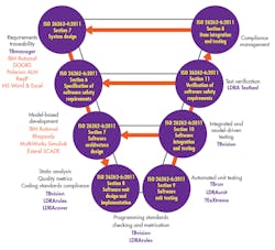
Beyond adherence to coding standards, fully integrated software tools can check and enforce guidelines for quality design of software units and facilitate their integration and testing according to the defined software architecture and the system’s requirements. Applying and enforcing such principles at the unit coding level makes it more certain that the units will fit and work together within the defined architecture. Ideally, an integrated tool suite should collate these automated facilities so that they can be applied to all stages of development in the standard “V” process model (Fig. 1) and can coordinate requirements traceability, analysis, and testing over all stages of product development.
1. Mapping the capabilities of an automated tool chain to the ISO 26262 process guidelines.
Static Analysis and Software Unit Testing
From a broad perspective, ISO 26262’s practices are aimed at making code more understandable, more reliable, less prone to error, and easier to test and maintain. For example, restricting the size of software components and their interfaces makes them easier to read, maintain, and test, and therefore less susceptible to error in the first place. Static analysis can check a host of guidelines to ensure that variables are initialized, global variables are not used, and recursion is avoided. The existence of global variables, for instance, can cause confusion in a large program and make testing more difficult. Applying static analysis throughout the code-implementation phase can highlight violations as they occur, and ultimately confirm that there are none present. In addition, tools can generate complexity metrics to make it possible to measure and control software component size, complexity, cohesion, and coupling (Fig. 2).
2. Static analysis can examine control and data coupling of a software unit and relate it to the system architecture.
Software unit testing demonstrates that each software unit (function or procedure) fulfills the unit design specifications and does not contain any undesired behavior. Once that is proven, unit integration testing demonstrates the continued correctness of that behavior as these units are deployed as part of a system, and then that this integration actually realizes the software architectural design laid out at the higher level. Perhaps the ultimate integration test is a system test, when all of the software is operated as a coherent whole.
Unit testing and unit integration testing uses this framework to provide a harness to execute a subset of the code base, and verify that the functionality of the software interfaces is in accordance with software design specification and requirements. That includes ensuring that only those requirements are met, and that the software does not include any unrequired (that is, undesired) functionality. This same unit test facility can be used to create fault-injection tests for functional safety, measure resource usage, and where applicable, ensure that auto-generated code behaves in accordance with the model from which it was derived.
While static analysis can perform an automated “inspection” of the source code to verify adherence to the ISO 26262 guidelines for coding and unit implementation, beyond that, the information derived from that static analysis can be used to provide a framework for dynamic analysis—the analysis of executed code. Ideally, all dynamic analysis should be implemented using the target hardware so that any issues resulting from its limitations are highlighted as early as possible. If target hardware is not available in the early phases of a project, the code should be executed in a simulated environment based on the verification specification. That can allow development to proceed with the caveat that testing on the actual target hardware will ultimately be needed.
Ensuring Traceability to Software Safety Requirements
Integration testing, then, is designed to ensure that all units work together and in accordance with the architectural design and the requirements. In the case of an ISO 26262-compliant project, that implies the verification of functions relating to the ISO 26262 software safety requirements as well as more generic functional requirements. Again, these tests can initially use a simulated environment, but ISO 26262 then calls for analysis of the differences between source and object code and between the test and the target environments in order to specify additional tests for ultimate use in the target environment. In any event, testing on the target hardware must be completed prior to certification.
Where tests fail, it is likely that code will need to be revised. Similarly, requirements can change part-way through a project. In either case, all affected units must be identified and all the associated unit and integration tests must be re-run. Fortunately, such regression tests can be automated and systematically re-applied to assure that any new functionality does not adversely affect any that is already implemented and proven.
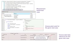
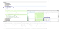
This constant attention to the faithful representation of requirements by the code is especially relevant to unit test and integration. The inputs and expected outputs for these tests are derived from the requirements, as are tests for fault testing and robustness (Fig. 3). As units are integrated into the context of their associated call trees, the same test data can be reused.
3. Requirements-based testing allows the developer to enter inputs and expected outputs in the LDRA tool suite. The outputs are captured along with structural coverage data and compared with the expected outputs.
Unit and integration testing with dynamic analysis ensures the software functions correctly, both as a unit and “playing well with others” when connected to other units in the overall program. However, in the latter context it is also necessary to evaluate the completeness of such testing as well as to make sure there is no unintended functionality. Function and call-coverage analysis tests to see that all calls have been made and all functions have been called. It is, however, necessary to more thoroughly examine the structure by executing statement and branch coverage, which assures that each statement has been executed at least once and that each possible branch from each decision point is taken at least once.
Where there are multiple conditions to consider at such a decision point, the number of possible combinations can soon lead to a situation where testing each of them is impractical. Modified Condition/Decision Coverage (MC/DC) is a technique that reduces the number of test cases required in such circumstances, calling only for testing to demonstrate that each condition can independently affect the result.
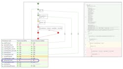
Coverage analysis at the unit level will verify the conditions within that unit but will obviously not exercise calls outside that unit. Unit tests, integration tests, and system tests can all contribute to the degree of coverage over the entire project (Fig. 4).
4. Structural coverage analysis of the application correlates the internal functions of the units and their interfaces with the architectural design of the system.
To place all of this into context: the functions of the software units are determined by the software architectural design, which is in turn determined by the requirements. Both the requirements and architecture, which define the units, also define the testing required by each of those units. In turn, when the units are integrated, they are tested to verify their functional interaction as well as their compliance to the software architectural design and—for ISO 26262—both functional and safety requirements.
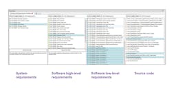
The requirements at the top of the V-model shown in Fig. 1 are often defined using specialized requirements tools such as IBM Rational DOORS, or modeling tools such as MathWorks Simulink. Having a software tool suite that interfaces with such tools can be an advantage in verifying the bidirectional traceability that is required by ISO 26262, even where modeling tools are used to automatically generate source code (Fig. 5). These auto-generated units are subject to the same rigorous testing, verification, and integration procedures as hand-coded units, legacy code, and open-source code.
5. The LDRA traceability function shows a detailed design linked upstream to software requirements and downstream to software units.
Automated Testing and Verification Tools Keep ISO 26262 Projects on Track
It is easy to think of development as a stage-by-stage process, with test coming somewhere after coding. However, regular testing during development complete with bi-directional requirements tracing is vital because the later a failure shows up, the higher the cost in both time and money.
With all this concurrent activity, maintaining an up-to-date handle on project and traceability status by traditional means is a logistical nightmare. For example, the possible cause of an integration test failure might be a contradiction in requirements, something that is much easier to deal with if recognized early. If it is later and the requirements need to be modified, it will have an inevitable ripple effect through the project. What other parts of the software are affected? How far back do you have to modify and test to be sure the change is covered?
A similar unhappy scenario accompanies a coding error discovered late in the day. What other units are dependent on that code? What if there is an incorrect specification in one of the requirements but unit tests have already been run and are now at least suspect? How do you find your way to know that everything has been fixed?
In such situations, manual requirements tracing will at some point break down. At the very best, it will still leave a sense of uncertainty. However you collate your requirements, whatever design approach you adopt, whether you develop model-generated or hand-generated code, automated testing and verification tools can do more than just report on the status of a particular development stage. An integrated tool suite can provide traceability between the requirements, the design, and the source code—from the lowest-level functions and their test results up to the specified requirements. Staying on track with ISO 26262 from bright idea to a reliable and safely running system needs constant attention with a flair for detail that only automated tools can deliver.

