Oscilloscope Triggering Advanced Course: Advanced Trigger Features
Download this article in PDF format.
Welcome to the Oscilloscope Triggering Advanced Course! In this series, I will walk you through the details of every corner of real-time oscilloscope trigger systems, and by the time we’re done, you’ll never need that AutoScale button again! Your co-workers will be stuck in the lab staring at auto-triggers all weekend while your scope is automagically catching glitches and protocol packets and emailing you the results! If you’re just joining us now, do yourself a favor and check out the first four articles in the series as well to learn about advanced trigger modes, protocol triggering, and trigger sequencing.
In this article, we’re going to explore some of the advanced features available in modern scope trigger systems. Rather than the trigger modes we’ve discussed in previous articles (see "Related" at the bottom of the article), the features described herein are more like modifiers and options used in conjunction with those modes to add functionality or convenience. The trigger mode is the cake; these features are the icing. Let’s get started!
Trigger Qualifiers
Trigger qualifiers are fairly common features on modern scopes. While the specifics of these features vary model to model, qualifiers are generally considered additional events outside of the trigger mode that must be true (in addition to the trigger-mode conditions being true) at the instant the trigger-mode condition is evaluated in order for the trigger to fire.
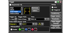
One common trigger qualifier is AND Qual. You might be wondering what’s up with the CAPITALIZATION of the word “AND,” it’s not a typo. “AND” is capitalized because it refers to the logical operation “AND” (or “&&” for software folks). AND Qual allows you to require that a certain logic pattern is true at the instant the main trigger condition is evaluated in order for the trigger to fire (Figs.1, 2, and 3).
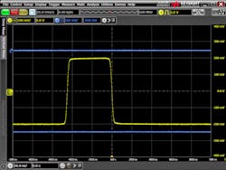
1. Here we see two asynchronous signals displayed on a Keysight Infiniium S-Series oscilloscope using pulse-width trigger mode on channel 1 to gate acquisition. Note that because our trigger is only relative to channel 1, the waveform behavior on channel 3 appears to be both low and high simultaneously. That’s because the scope is showing us the result of many individual triggers plotted on top of each other. In some of those triggers, the channel 3 waveform is low, and on others it’s high. When plotted together, it appears to be both.
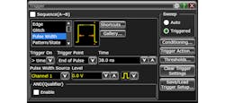
2. Shown is the trigger setup dialog on an Infiniium S-Series scope for the waveforms displayed in Fig. 1.
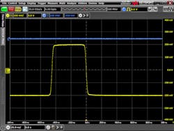
3. Using AND Qual, we restricted the pulse-width trigger events on channel 1 that we’re interested in to only those that occur while channel 3 is high.
The AND Qual logic pattern is essentially the same as the type of pattern defined by the user in pattern trigger mode (see the first article in this series for details on pattern trigger mode). The user may select “high,” “low,” or “don’t care” for a number of possible input signals, with “high” and “low” referring to the signal relative to its configured trigger threshold (Fig. 4).
4. Here we see the trigger setup dialog again. However, this time, AND Qual is enabled for channel 3 high. In this case, the “1” in the box for channel 3 means “high,” while a “0” would mean “low.” High and low in this context refer to the signal being above or below the threshold configured for that channel. On this scope, those thresholds are configurable in the thresholds dialog, which the user can reach by clicking the “Thresholds...” button on the right side of the trigger setup dialog.
Holdoff
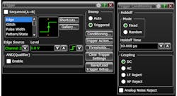
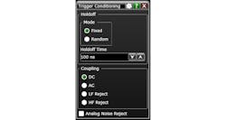
Trigger holdoff is defined as the amount of time that must pass after the scope finishes completing the acquisition of the waveform from the previous trigger before the trigger system re-arms for the next cycle. Every oscilloscope with an analog trigger system has holdoff, but some scopes allow the user to adjust the amount of holdoff time (Fig. 5) or even set parameters to randomize it. So why should you care about holdoff? When used correctly, holdoff can help qualify trigger events in two ways:
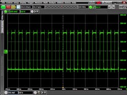
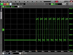
- Clean up bursty data on screen: Holdoff time can be increased to swallow data bursts, ensuring that the scope triggers consistently on the beginning of the burst each time (Figs. 6 and 7).
- Avoid trigger synchronization: Every so often, the parameters of your input signal and the configuration of your scope hardware can align and cause the trigger to fire synchronously to some aspect of your input signal. This can cause you to miss seeing important characteristics of the signal. By enabling randomized holdoff, the scope will use a different delay after each trigger event, ensuring you get a more accurate picture of what your signal is really doing.
5. These are the trigger setup and trigger conditioning dialogs on an Infiniium S-Series scope for the waveforms displayed in Fig. 7. By increasing trigger holdoff time to 10 μs, we were able to see the true nature of the signal. The trigger conditioning dialog is accessed by clicking on the “Conditioning…” button on the right side of the trigger setup dialog.
6. Here we see what appears to be a square wave displayed on channel 2 of our S-Series scope, but it looks a little odd.
7. By increasing the trigger holdoff time, we see that the signal on channel 2 is actually a burst!
Aux Trigger
Almost all modern oscilloscopes have an auxiliary trigger input; a signal input that connects to the trigger system but not the acquisition system. Typically, aux trigger can only be used as a source for simple edge trigger; nevertheless, it comes in handy from time to time. In particular, aux trigger is helpful when using the scope as a digitizer in an automated setting. That’s because it allows you to synchronize when the trigger fires without using an acquisition channel, leaving you all of the scope input channels for the data you’re trying to capture.
The aux trigger input is also typically more robust and can handle higher-amplitude signals than the main scope input channels. This is particularly true on high-performance, high-bandwidth scopes with delicate analog preamps, and can come in handy when trying to use the scope alongside industrial equipment.
Line Trigger
Line trigger is essentially the same as aux trigger described above, except instead of a signal-input connector, it’s a hardwired connection to the scope’s input ac power source. Line trigger is less common these days than it was a decade or two ago. However, on scopes that have line trigger, it can be useful if you’re trying to capture events that coincide with the ac input feeding the scope.
Coupling and Filtering
Trigger coupling is the trigger path counterpart to input coupling on the acquisition path, typically referred to as AC or DC. DC trigger coupling will deliver the entire frequency content of the input signal (up to the bandwidth of the trigger system) to the trigger, including any DC offset, whereas AC coupling will block any DC component.
In addition to trigger coupling settings, some scopes also have additional filtering selections like “Low-Frequency Reject,” “High Pass,” etc. (Fig. 8). Like AC coupling, these are essentially just filters, applied in the trigger path only, that can help isolate the signals you’re interested in.
8. This is the trigger conditioning dialog on an S-Series scope. Note that this scope has options of AC and DC coupling, as well as low-frequency and high-frequency reject. Trigger conditioning and filtering options will vary scope to scope.
AC coupling in particular can be helpful in the trigger path if you find yourself probing a handful of signals with different DC offsets. The DC-coupled input will still show you the correct offset onscreen, while the AC-coupled trigger is capable of grabbing edges of the signal without adjusting the threshold due to the lack of DC content reaching the trigger.
Trigger Actions
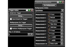
Trigger actions are exactly what they sound like—special actions or events that you can configure to occur anytime there’s a trigger. The details and availability of trigger actions vary quite a bit from scope to scope. It’s worth your time to find out if your scope has features like this, because they can be a huge time saver (Fig. 9). For instance, my favorite trigger action is the email on trigger feature; if you’re trying to capture an infrequent event, just set your scope up and leave for the day, or even the week! When the trigger occurs, your scope will email you with the details.
9. Here we see some of the options available as trigger actions on an Infiniium S-Series scope.
That wraps up our discussion of advanced trigger features. If you haven’t yet, be sure to check out the first four articles in the series, and stay tuned for the series finale, where we’ll dive into trigger performance characteristics.
