Download this article in PDF format.
If you’ve been tuned in to Electonic Design’s articles this past year in the test & measurement arena, you’re probably aware of a series by Colin Mattson (Keysight Technologies) on advanced oscilloscope triggering techniques. In the first article, he elucidates on pulse and pattern modes, where the characteristics of a pulse and the uniqueness of a pattern are utilized as the impetus of signal acquisition.
In part two, he delves into edge-mode triggering, where the edge characteristics of a signal are used to mark the trigger for waveform capture. In part three, he covers protocol triggering, where the patterns adhered to by a protocol (such as I2C and SPI) are detected.
A comment on one of his articles reads:
“Email on trigger! I thought you were joking, but that’s an incredibly weird and fun capability. As someone who has spent a lot of time waiting for powerline transients to happen (or not), that’s a really nice idea.” – Ed Price
I, too, have not come across (directly with) an oscilloscope that’s capable of sending an email wirelessly (IoT-mania?) after a trigger event. In my opinion, such a system would come at a hefty cost. At least, consider the operating expense, the wear-and-tear that will decrease oscilloscope lifespan, and the risk of false alarm.
But a feasible solution to this problem is fun to think about. Perhaps a high-voltage detector would do nicely, its output interfaced to an LVS, then an Arduino hooked to a cheap GSM module (for text messaging) or an ESP8266 (for email). It would be more economical in terms of both money and space. Does anyone have any good ideas on this?
Frequency-Domain Trigger
I’ve seen scopes that run on a Windows operating system, so it should be possible for a third party to program the scope to send an email given a trigger event, out an Ethernet cable or Wi-Fi transceiver, if it can be ported to one. Speaking of all these trigger mechanisms, I’ve been pondering the need for an oscilloscope trigger system that operates in the frequency domain. What if we wanted to monitor a signal that oscillates at a specific frequency, or is characterized by a particular set of frequencies, for a limited amount of time, in the time domain?
You may now be scratching your head, thinking “Wait, isn’t that the job of a spectrum analyzer?”
Well, not exactly. Even though the trigger is in the frequency domain, the waveform will still be in the time domain.
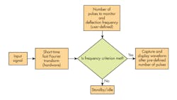
But how can an oscilloscope do that? There’s a generic math function that displays the fast Fourier transform (FFT) of a signal, but it’s implemented in software and thus becomes impractical for real-time signals. The figure illustrates a possible implementation.
Here's the simple flow of the algorithm that would be used in frequency-domain triggering.
A real-time signal will be fed to a digital signal processor (DSP) implementing the short-time Fourier transform (STFT). The window’s length will be defined by the user and must not be shorter than twice the desired wavelength of the highest frequency (remember aliasing and the Nyquist criterion). As the signal is fed to the DSP, the waveform is simultaneously sampled and stored in a variable-sized buffer depending on window length.
At the output of the DSP, the frequency pattern is compared with a reference, also defined by the user. If the comparison is a match, then the scope will display the contents of the buffer. Otherwise, nothing is displayed on the graticule and the buffer is emptied and reloaded. The sets of data that go into and out of the buffer must not be contiguous, but overlapping.
The Need for Speed
It sounds simple, but the real challenge lies in the entire system’s speed. Achieving minimal latency requires simplification, pipelining, and optimization at all levels of the design. Can I implement this portion of the system in hardware? Can I remove this portion of code that will go to the DSP without sacrificing accuracy? Can I pipeline this batch of data to this part of the STFT algorithm while the decision-making for frequency of the previous batch is ongoing? In addition to these considerations, the answers are further limited by the famous tradeoff with cost.
So, what is the trigger system described above good for? One application could involve the analysis of sporadic interference and noise. Say, for instance, a portion of the board where a 200-kHz data signal is supposed to be traveling always ends up with some of its packet interpreted as garbage. Of course, given modern error detection and correction techniques, the chances that such a phenomenon will occur is slim.
However, if it’s known that a source nearby emits a signal with harmonics of 190 kHz, 200 kHz, etc., then we can program the scope to monitor for such signals and determine whether the sources are indeed the cause of trouble. The common method for this is to use a spectrum analyzer, and then determine the location of the noise source via triangulation.
In the end, all of the above may be a pile of wish-wash thinking. But who knows, they may perchance serve as a cornerstone for another solution to another problem.


