The Effect of Wire-Path Resistance on Battery Measurements
Download this article in PDF format.
Proper wiring and probing/contacting are critical to making successful measurements. When testing cells or batteries, using good engineering practices is important to avoid noise pickup, signal degradation, and unwanted voltage drops through wiring and contact resistances.
If you’re testing cells or batteries at high currents, resistance will be a critical consideration. As test currents rise, the resistance in the wires and in the contacts will cause significant voltage drops.
Wire-Path Resistance Voltage Drops are Problematic During Battery Discharge
These voltage drops can cause problems during the discharge of a battery into an electronic load, as electronic loads have a minimum operating voltage. Note when I say electronic load, this could be a benchtop electronic load or the discharge circuits in a battery tester (sometimes called a battery cycler). As the battery voltage drops during discharge, the battery voltage may approach the minimum operating voltage of the electronic load.
If large voltage drops occur in the wiring, then the voltage at the input to the electronic load may drop below its rated minimum operating voltage. When the electronic load is operated below its minimum operating voltage, the available current will be derated and you may not be able to draw the required current out of the battery.
Comparing Two Discharging-Cell Cases
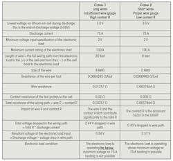
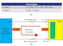
Let’s look at the impact of wire and contact resistance for two cases of discharging a high capacity lithium-ion cell (see table). The figure shows a schematic diagram of the discharge setup.
The figure shows a schematic diagram of the discharge setup.
Impact of wire and contact resistance of voltage at input (a) to electronic load or battery discharger (b).
So, the keys to successful discharge operation are:
- Use the shortest wire possible.
- Use thick wires to minimize the voltage drop in the wires.
- Use good quality probes to minimize contact resistance.
These are necessary to keep the total resistance low so that the voltage drop is minimal at high current during discharge.
Other Considerations
Is the cable well-constructed or does flexing the cable change the resistance? Inconsistent wire resistance from channel to channel can make some channels work properly because they meet wire resistance criteria to keep the voltage above the electronic load minimum input voltage when drawing high current. Meanwhile, other channels have too much resistance and thus don’t work properly, causing channel-to-channel behavior variation.
Is the contact resistance changing over time? Contacts can become worn out and pin-type probes can go out of alignment, causing inconsistent pressure and inconsistent resistance. Contacts also may become dirty from dust and chemicals. Monitoring the number of cycles of use and performing preventative maintenance (cleaning, alignment, and replacement) can reduce these effects.
Furthermore, the batteries themselves could be a cause of inconsistent contact resistance because the battery contacts may be oxidized. Contacts are often made of materials that easily build up an oxide coating over time.
Contact Resistance Impact on Voltage Measurements
Now let’s look at a measurement of voltage. Is contact resistance important there? Can measurements of cell voltage be distorted or impacted by contact resistance?
The short answer is no—contact resistance will not impact the measurement of voltage. Voltage measurements are made with the DMM configured with high impedance input. For a typical DMM measuring voltage, the input impedance is hundreds of megohms or even gigaohms. Because the input impedance is so high, virtually no current flows into the DMM measurement terminals. If no current is flowing, then resistance in the path has no effect on measurement.
But what about a battery tester? Is the input impedance as high on a battery tester as found on DMM?
Achieving very high input impedance on a measurement instrument is challenging. Most battery testers measure voltage in the same manner as a DMM, although the input impedance is not usually gigaohms because battery testers aren’t trying to measure the wide range of devices that a standard DMM is expected to measure.
For example, the Keysight BT2152A is a battery test instrument focused on measuring self-discharge of lithium-ion rechargeable cells. (For more information about measuring self-discharge of lithium-ion cells, click here). When measuring cell voltage with the BT2152A, the input impedance is 10 MΩ. At the maximum cell voltage of 4.2 V (typical) and 10 MΩ of input impedance, the current flow into the BT2152A’s input is 420 nA. This value is found using Ohm’s law of V = I*R or I = V/R, so for a 4.2-V cell connected to a measurement system with 10-MΩ input impedance, current is calculated as 4.2 V/10 MΩ, or 420 nA.
Since the input impedance is 10 MΩ, only 420 nA of current will flow. With total wire-path resistances of far under 1 Ω (see table), the voltage drop across the wire is under 420 nV. Even if wire and contact resistances were to become thousands of times bigger than what’s shown in the table and climb to 10 Ω, the voltage drop in the wire resistance would jump to 4.2 µV, which is insignificant measurement error compared to the 4.2 V being measured on the cell. As you can see, thanks to the high impedance input, the resistance of the wires and contacts don’t impact the voltage measurement.
However, whenever you’re making voltage measurements, noise pickup needs to be minimized by proper grounding and shielding, but that’s the subject for another article.
About the Author
Bob Zollo
Solution Architect for Battery Testing, Electronic Industrial Solutions Group
Bob Zollo is solution architect for battery testing for energy and automotive solutions in the Electronic Industrial Solutions Group of Keysight Technologies. Bob has been with Keysight since 1984 and holds a degree in electrical engineering from Stevens Institute of Technology, Hoboken, N.J. He can be contacted at [email protected].


