Designing Isolated Gate Drivers for SiC MOSFETs in Traction Inverters
Members can download this article in PDF format.
Traction inverters based on silicon insulated-gate bipolar transistors (IGBTs) have been the go-to technology for electric vehicles (EVs). However, to improve the power efficiency of EVs, these devices must be more efficient, too. One metric is to replace higher-power IGBTs with more efficient and higher-temperature operation of silicon-carbide metal-oxide-semiconductor field-effect transistors (SiC MOSFETs). This change in design has a notable effect on both power savings and safety.
Traction inverters convert dc power from an on-board, high-voltage (HV) battery system into power for driving—in this case, the main motor, or motors, of an EV. However, there’s a catch. Compared to IGBTs, SiC MOSFETs have a totally different set of input characteristics.
Therefore, isolated gate drivers that work with IGBTs will not be compatible with SiC MOSFETs. To overcome this problem and take advantage of the SiC MOSFET’s, lower power, faster speed, and other benefits, Texas Instruments developed a new series of isolation gate drivers, including the UCC5880-Q1. Figure 1 shows the advantages of using SiC over silicon.Significance of the Isolated Gate Driver
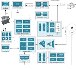
TI isolated gate drivers are the integral components that interface with the SiC MOSFETs in traction inverters (Fig. 2; note the galvanic isolation components).
High-current, real-time variable gate-driver ICs, such as the UCC5880-Q1, are designed to minimize the power loss within the SiC MOSFET and supply the high current necessary to drive it. These ICs are responsible for delivering the high and low sides of the SiC MOSFET and providing the input/output galvanic isolation needed to protect the user from the system. They also shield against various fault conditions and add monitoring capabilities.
Isolated gate-driver design requires a lower isolation voltage due to the lower voltage levels associated with SiC MOSFETs. One benefit is that lower isolation voltage and faster switching speed improves the traction inverter’s efficiency and performance. It also optimizes the galvanic isolation between the system and the user.
Driver ICs and SiC MOSFET Design
A number of primary design challenges come with using SIC MOSFETs in traction inverters. Fundamentally, the SiC MOSFETs internal resistance (RDS(on)) must be kept as low as possible. Because the RDS is proportional to the power loss across MOSFETs (Ohm’s law), they’re more efficient and generate less heat.
Second, SiC MOSFETs have an intrinsically low gate capacitance. When designing the impedance-matching network of the gate driver, its output impedance needs to be much lower than the input impedance of the SiC MOSFET. If the impedance is too high, the gate driver can’t supply sufficient current to charge and discharge the gate capacitance of the SiC MOSFET quickly, even with high-current devices like the UCC5880-Q1.
However, an important design consideration is that most systems use more than one SiC MOSFET. In these cases, modifiers such as P = (Freq × Qg × Vgs(total) × N) come into the design equation, where P is the average power, Freq is the switching frequency, Qg is the total gate charge, Vgs(total) is the total gate voltage swing, and N is the number of devices in parallel.
Of course, other standard design parameters need to be considered as well. These can be easily found in TI device datasheets.
Some tips for accomplishing this include:
- Optimal gate resistor selection: The value of the gate resistor can be chosen to match driver output impedance with the input impedance of the SiC MOSFET.
- Use a real-time, variable-output gate driver with adjustable parameters. The UCC5880-Q1 offers this real-time variable gate-drive strength function.
- Adding an external matching network: An external matching network can be added between the gate driver and the SiC MOSFET to provide the required impedance matching if no other solution works.
The Safety Aspect
There are multiple points for failure in EVs. Isolated gate drivers provide the additional benefit of isolation between the system and the user. These drivers are a part of “functional safety.” This refers to the system’s electrical and electronic system hazards, rather than the typical product safety, which is the overarching consideration. Therefore, it has a different criterion than product safety.
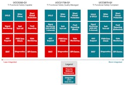
Since traction inverters are such critical components, all TI gate drivers are certified for functional safety to some degree. The least complex are Functional Safety capable; the most complex are Functional Safety Compliant. This compliance is based on ISO 26262.
Depending on the model, safety features can be either integrated or external to the gate driver. TI isolated gate drivers use a variety of approaches to address functional safety across the component line. The higher the compliance, the more integrated safety features are available. (Fig. 3).
Choosing the right product depends on the design criterion. All of TI’s gate drivers conform to a minimum TI functional-safety level. Some models such as the UCC5870-Q1 have a built-in self-test (BIST) as well as various ways to assess risk.
EV failure modes can traverse a wide gamut of conditions, both mechanical and electrical. Functional safety focuses on analyzing the cause and implementing supported safety mechanisms as defined by the model’s features.
Most faults are random, though. Thus, when deciding on the IGBT’s requirement for reporting and logging, be sure to understand each model’s functional-safety category and how each model supports the various reporting options.
Conclusion
TI gate drivers are the next level of technology and performance for traction inverter systems. They integrate novel designs and critical safety features. As the EV industry matures, it’s critical that EVs are efficient, reliable, and safe. Isolated gate drivers play a significant role in achieving that goal.


