Design Tools and Resources Help Maintain Your Analog Edge
Members can download this article in PDF format.
Analog and power-supply design projects can be daunting. Adding the logic required for mixed-signal designs often further complicates the development effort. Fortunately, you can take a divide-and-conquer approach to simplify the task.
Begin with a collection of analog subcircuits that you can adapt and combine into more complex subsystems. For the power-supply portion of your design, start with an online design tool that will help optimize efficiency, solution size, and cost. And finally, you can find brief, concise online tutorials to refresh your knowledge of the logic components you might want to add to your mixed-signal designs.
Analog Cookbooks
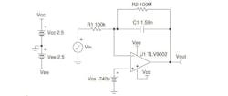
To help get you started on analog subsystem design, Texas Instruments offers two analog cookbooks—one offering more than 60 amplifier recipes and the other featuring over 40 data-converter recipes. The amplifier book presents a variety of basic circuits, including a buffer; inverting, noninverting, difference, and instrumentation amplifiers; and differentiator and integrator circuits. Figure 1 shows an integrator, which has the following transfer function:
The cookbook offers several recommendations for this circuit—use a CMOS op amp to minimize input bias-current errors, for example, and connect an adjustable reference voltage to cancel input offset voltage errors.
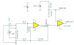
Beyond the basics, the amplifier cookbook describes sensing amplifiers, signal sources, filters, nonlinear and signal-conditioning circuits, and comparators. Figure 2 shows an example in this last category. It’s a high-speed, low-side, overcurrent-detection circuit that employs a zero-drift fast-settling amplifier and high-speed comparator.
The amplifier provides a differential voltage measurement across the sense resistor through which the measured current flows, eliminating any errors that could occur if power-supply ground and load ground differ. For the values shown, the overcurrent threshold is 1 A.
The amplifier cookbook also describes circuits for data-acquisition and audio applications. It concludes by describing TI’s MSP430 microcontrollers that combine signal-chain elements such as op amps and data converters into a peripheral called smart analog combo (SAC).
The data-converter cookbook addresses both analog-to-digital and digital-to-analog converters (ADCs and DACs), often combining the converters with circuits similar to those described in the amplifier cookbook. For example, Figure 3 depicts an ADC circuit in which an instrumentation amplifier (U1) converts a low-level 22-mV sensor signal to a 10-V output. Because the ADC’s input capacitance prevents the instrumentation amplifier from driving it directly at full bandwidth, an op amp (U2) serves as a buffer, enabling the ADC to operate at its highest sample rate.
Also for ADCs, the cookbook describes circuits optimized for power, size, and cost. It presents level-translation input-drive circuits; input-protection, filtering, and isolation circuits; and auxiliary circuits.
For DACs, the cookbook describes devices configured as current or voltage sources as well as auxiliary and biasing circuits, and it describes the use of DACs in audio applications. Figure 4, for example, shows an audio DAC with an active-filter circuit optimized for a 44.1-kHz sample rate.
Power-Supply Design with WEBENCH
When you’re ready to develop your power-supply subsystem, you can employ TI’s WEBENCH Circuit Designer online tool, which addresses active filters as well as power supplies. When you begin a power-supply design, WEBENCH presents an intuitive input form, in which you enter your input voltage and frequency as well as your DC output voltage and current. You can also indicate whether you want your design to be balanced or optimized for cost, efficiency, or footprint.
You then press “VIEW DESIGNS” to see dozens of relevant circuits (Fig. 5) incorporating a variety of TI power-conversion components—ranging from flyback controllers to current-mode pulse-width-modulation (PWM) controllers. You’re able to filter the designs with respect to bill-of-materials (BOM) cost and count, efficiency, footprint, switching frequency, output ripple voltage, crossover frequency, phase margin, circuit topology, control mode, IC package type, and other features.
You can customize each circuit and perform electrical simulation (with optional Monte Carlo or corner-case analysis) as you zoom in on the optimum configuration for your application. When finished, the design can be exported to your favorite CAD tool.
Adding Logic to Circuits
Frequently, you will want to add logic to your circuits to monitor error signals, trigger an alarm, enable or disable a device, convert a momentary switch to a toggle switch, debounce a switch, control an indicator LED, or provide voltage translation. To help you implement such functions, TI offers the Logic Minute video series, which gets you up to speed in just a minute or two.
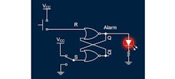
Figure 6 shows one example, where two NOR gates configured as a set-reset (S-R) flip-flop are able to detect a transient anomaly and illuminate an LED. A two-pole switch (lower left) connected to the latch’s S input simulates the anomaly in this example. When the switch transitions from ground to VCC, flip-flop output Q goes high and the LED turns on. When the anomaly clears (i.e., the two-pole switch again grounds the S input), the LED continues in the on state until the flip-flop is reset using the pushbutton in the upper left, which connects the flip-flop R input to VCC.
In a real-world configuration, a comparator output such as the COMP_OUT signal in Figure 2 could replace the two-pole switch. In addition, the flip-flop Q output could drive an input pin to an MCU that could take appropriate action (reduce output voltage in response to an overcurrent condition, for example) and reset the flip-flop, possibly after a time delay.
Conclusion
You can simplify complex circuit designs by beginning with subcircuits that are then combined into larger subsystems and systems. TI offers circuit cookbooks as well as online design tools and learning resources to help you quickly and accurately complete analog as well as power-supply and mixed-signal designs.


