How to Push ADAS Processors Beyond 100 A While Ensuring Functional Safety
Members can download this article in PDF format.
Vehicles are taking on an increasing number of advanced capabilities, including adaptive cruise control, forward collision warning, automatic high-beam control, driver monitoring, parking assistance, vehicle-to-everything (V2X) communications, and full autonomous driving. As vehicles offer more and more of these features, they require considerable processing power, and modern advanced driver-assistance systems (ADAS) can draw in excess of 100 A.
Choosing the processors and power supplies that deliver the necessary voltages and currents while minimizing electromagnetic interference (EMI) can present challenges.
Sponsored Resources
- How to deliver current beyond 100 A…
- Automotive 2.7V to 6V Input
- Automotive, 4V to 80V, 100% Duty Cycle Capable.
ADAS System-on-Chip
One processor suitable for use in ADAS applications is Texas Instruments’ TDA4VH-Q1 automotive system-on-chip (SoC). Combining eight Arm Cortex-A72 application cores, it offers depth-and-motion, video-encode/decode, vision-preprocessing, and deep-learning hardware accelerators. To help you pinpoint the exact current and voltage requirements of your specific TDA4VH-Q1 application, TI offers a power-estimation tool.
After determining the requirements of your specific ADAS, you can use TPS62876-Q1 buck converters to deliver the necessary power. These converters come with maximum current ratings from 15 to 30 A, but they offer a stacking feature that enables them to work together to provide currents beyond 100 A.
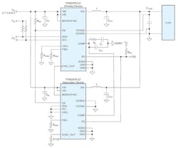
Figure 1 shows two TPS62876-Q1 devices in a stacked configuration. Here, the lower device operates in secondary mode, programmed by tying its SYNC_OUT pin to ground. For optimal current sharing in stack mode, both devices should operate at the same switching frequency, as programmed via each device’s FSEL pin.
Other features of the TPS62876-Q1 include droop compensation, which improves load-transient tolerance while minimizing the required output capacitance to reduce cost and improve power density. The devices also have a remote-sensing capability that lets them power SoCs with tight power-supply voltage tolerances.
In addition, a spread-spectrum clocking function helps to minimize EMI by modulating the switching frequency ±10% around the nominal value. Finally, the devices can report overtemperature and overcurrent warnings over their I2C interfaces.
Of course, functional safety is a critical aspect of ADAS and other automotive applications. The TPS62876-Q1 falls into TI’s Functional Safety-Capable product category and comes with documentation that addresses failure-in-time rates and component failure modes.
Dual-Phase Step-Down Converter
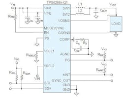
An alternative is to use a device in the TPS6288x-Q1 family of dual-phase step-down converters (Fig. 2). These converters are available with 12-, 20-, 24-, and 30-A ratings and have a stacking feature that enables five devices to operate in parallel; thus, you can deploy five of the 30-A TPS62883-Q1 versions for a total 150-A rating. The input voltage range is 2.7 to 6 V. Three output-voltage ranges extend from 0.4 to 1.2 V, selected via the devices’ VSELx pins or I2C interfaces. Their switching frequencies are factory-programmed to 2.25 MHz. You can optionally program them to 1.5, 2.5, or 3 MHz and synchronize them to an external clock.
All devices in the family are dual phase, which reduces input and output voltage ripple and enables the use of small inductors, saving cost and increasing power density. At medium and heavy loads, the devices operate in pulse-width-modulation (PWM) mode and switch to a discontinuous conduction mode at light loads to maintain high efficiency. Optionally, they can be configured to operate in PWM mode under all load conditions, thereby minimizing output voltage ripple across all load ranges.
Other features include adaptive/dynamic voltage scaling, differential remote sensing, overcurrent protection, and optional spread-spectrum clocking. The TPS6288x-Q1 devices fit into TI’s Functional Safety-Compliant category and come with documentation to support designs up to the ISO 26262 standard’s Automotive Safety Integrity Level (ASIL) D.
High Input Voltages
For high-input-voltage applications, TI offers the LM5137F-Q1 dual-channel synchronous buck controller. Thanks to its 80-V input rating, the controller can perform direct conversion from 12-, 24-, or 48-V automotive buses down to low-voltage rails as low as 0.8 V, thereby reducing cost and complexity. Each device includes two interleaved synchronous buck channels that can be configured as dual outputs or a single multiphase output. The devices are stackable up to four phases.
The LM5137F-Q1 has several features that help minimize EMI and facilitate compliance with relevant EMI standards. It includes adaptively timed high-current MOSFET gate drivers that minimize EMI at high input voltages and switching frequencies while also reducing switching losses. The two-output configurations support 180-degree interleaved operation to reduce input-capacitor ripple current and EMI filter size.
In addition, the controller includes a programmable, dual-random, spread-spectrum function, and its resistor-adjustable switching frequencies can be synchronized to an external clock to eliminate beat frequencies. Like the TPS6288x-Q1, the LM5137F-Q1 supports functional-safety designs up to ASIL D.
Buck Controller Evaluation Module
To help you get started with the LM5137F-Q1, TI offers the LM5137F-Q1-EVM12V evaluation module (EVM), which operates over a 36- to 72-V input range and delivers a 12-V, 20-A output. You can customize the output voltage from 3.3 to 20 V by altering feedback-resistor values. The module comes with an electrolytic capacitor for parallel damping and an input p-stage EMI filter.
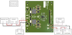
Figure 3 shows a recommended test setup for the EVM. TI recommends using voltmeters with input impedances of 100 MW and setting ammeter aperture times to 1 second. To measure output voltage ripple, use a 20-MHz oscilloscope in AC-coupling mode, place the scope probe on the positive terminal of the output capacitor, and connect the probe ground lead to the capacitor’s negative terminal.
Conclusion
As increasingly sophisticated vehicles take on more advanced driver-assistance features extending all the way to autonomous operation, they require ADAS that can draw in excess of 100 A. TI offers a lineup of buck converters and controllers that can deliver the necessary currents while minimizing EMI and meeting functional-safety requirements. The company also offers evaluation modules that can help you get started and keep your designs on the right track.
Sponsored Resources


