Circuit Generates High-Frequency Sine/Cosine Waves From Square-Wave Input
This file type includes high resolution graphics and schematics.
Although quite a few direct digital synthesis (DDS) ICs can generate high-frequency sine waves, their complexity excludes them from many designs. However, designers can use simple high-frequency CMOS logic and two switched-capacitor filters to create a sine/cosine generator. With newer filters, a 1-MHz output at 1.7 V p-p is possible.
Related Articles
- Kicking Back At High-Speed Unbuffered ADCs
- Switched-Capacitor-Based Bandpass Filter Boasts (Nearly) Rectangular Shape
- Digitally Tunable Capacitor Lets You Build Variable Filters, Z-Matches, And More
The example circuit uses an MSHFS6 5-V, low-power 12.5:1 switched-capacitor filter with selectable Butterworth, Bessel, or elliptic filters in the lowpass mode and full-, 1/3-, or 1/6-octave filters in the bandpass mode. Since the lowpass mode would cause a 3-dB loss of the signal output, the circuit uses the 1/6-octave bandpass filter, which is selected by tying pins 1 and 3 high on the MSHFS6 (Fig. 1).
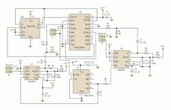
Two separate divider circuits are used. The 74HC393A divides the 50-MHz clock to 12.5 MHz. The 74HC390A is a dual divide-by-2 and divide-by-5 device. By combining the 74HC390 with the 74HC74A dual flip-flop, the 50-MHz clock can be divided to 500-kHz.
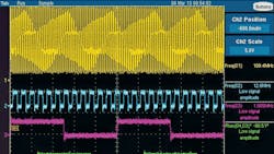
The 74HC74A provides a Q and /Q output at half the frequency of the divide-by-25 ouput of the 74HC390A. Dividing the 74HC74A output by 2 with the divide-by-2 blocks in the 74HC390A creates two square waves –90° apart. Figure 2 shows a 100-MHz square wave input, a 12.5-MHz output for the filter clock, and 1-MHz sine and –cosine square-wave output before the dividers.
Resistor-divider circuits reduce the amplitude from rail-to rail to prevent generation of distortion in the filters. The use of ac coupling at the MSHFS6 filter inputs ensures smoothed square waves centered around the filters’ analog ground.
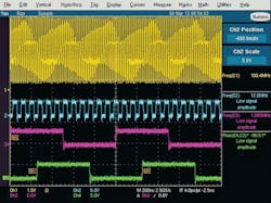
Figure 3 shows the output of the two filters with an input clock of nearly 50 MHz. If the inverted cosine is not acceptable, an op amp at the cosine filter output or the inverter at pin 13 of the 74HC390A can correct it.
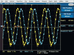
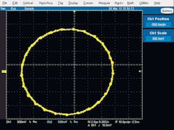
The Lissajous curve for the two outputs (Fig. 4) indicates that the phase circle matches the 89.1° reading in Figure 3. Using a Krohn-Hite 6900B distortion analyzer and a 1-MHz Krohn Hite lowpass filter (to remove the clock), the circuit’s total harmonic distortion on the sine output was only 0.1%.
Although the 74HC390A and 74HC393A have a guaranteed maximum operating frequency of 50 MHz at 6 V, Mixed Signal Integration Corp. and other companies have found that spec to be very conservative.
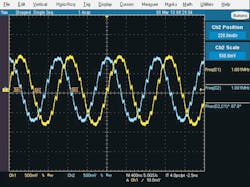
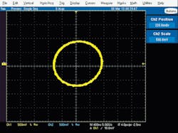
In this application, a 100-MHz input clock achieved the desired divide-by-4 and divide-by-100 needed to operate the newer MSVHFS6 switched-capacitor filter at 3.3 V. The only change needed was to reduce VDD to 3.3 V and replace the 5-V MSHFS6 filters with the 3.3-V MSVHFS6. The input clock was increased to 100 MHz. Figures 5 and 6 show the filter outputs’ phase relationship in time and as a Lissajous curve.
John R. Amrbose is the vice president of applications and system engineering at Mixed Signal Integration Corp. He can be reached at [email protected].
This file type includes high resolution graphics and schematics.
About the Author
John Ambrose
Vice President of Engineering and System Engineering
John R. Amrbose is the vice president of applications and system engineering at Mixed Signal Integration Corp. He can be reached at [email protected].
Comment About the Article
To join the conversation, and become an exclusive member of Electronic Design, create an account today!

Leaders relevant to this article: