What’s All This Bias Current Stuff, Anyhow?

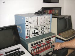
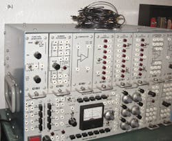
Bob Pease got an e-mail in 2006 from an engineer who was having trouble with an integrator circuit. Amplifiers are often called op amps because they were originally used as operational amplifiers. These amplifiers performed mathematical operations in analog computers (Fig. 1).
Integration is one of the functions that you can create by wiring a capacitor into the feedback loop of an amplifier. The very word “integration” implies you are putting together or adding up a signal. Indeed, the voltage output of an integrator is equal to the area of the signal that you have applied to the input (Fig. 2).
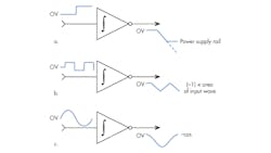
To make an amplifier integrate its input signal, you put a capacitor in the feedback loop (Fig. 3). The input resistor you select turns a voltage into a current. The current becomes charge on the capacitor. That charge creates a voltage. A fixed voltage across a resistor makes a constant current. A constant current into a capacitor creates a linear ramp.
Related Articles
- What's All This Capacitive Loading Stuff, Anyhow?
- What's All This Meter Accuracy Stuff, Anyhow?
- What's All This Solenoid Driver Stuff, Anyhow
Remember, the negative pin of the op amp is at virtual ground since the positive pin is grounded. This means a dc voltage across the input resistor will not change no matter what the output is doing—at least until the amp output hits a power supply rail. So, a constant input voltage will just keep charging and charging the capacitor until the output hits the power supply rail.
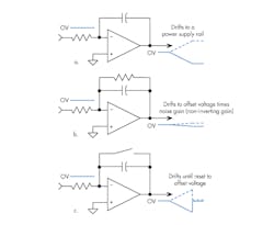
Your integrator circuit then needs to work on a signal with no dc component. Or, if there is a dc component, you have to reset the capacitor periodically by shorting it out, perhaps with a JFET. Now here is the bad news. There is always a dc component. Amplifiers are not perfect, so there is always a small bias current coming out or going into the input pins.
This file type includes high resolution graphics and schematics when applicable.
Pease To The Rescue
This was the problem that the engineer who wrote Bob Pease had. His integrator kept drifting because he did not realize that the feedback capacitor cannot distinguish from current coming at it from an input signal versus current that is leaking from the input pins.
The engineer titled his email to Pease “A small problem.” Yet bias current can be a very big problem, especially in low-level or electrometer applications where you are trying to measure charge. He wrote:
“Dear Bob; I have been working on a charge amplifier circuit using the LMC660 op amps for a constant charge input, but have been unable to get a steady output. The constant charge source is made by connecting a cap in series with a battery. My design consists of an integrator at the input with only a cap in the feedback path (without any resistor in parallel except the cap’s internal resistance).”
Bob was remarkably patient for not having a schematic or a better description. He asked some questions and then explained that the problem was caused by amplifier bias current:
“What value is this C? Did you buy it, or make it, or is it inherent in your system?” Pease almost always needed more information than his readers gave him. He reiterated, “What value is this C? This ‘charge-amplifier’ has to be re-set at some suitable times. Otherwise it will drift. There are no amplifiers in the world that can do this, on a dc basis, without any reset. Any time you ask the output of this charge amplifier to not drift, you are making an unreasonable demand on your system. What is the frequency characteristic of your signal? How big is it? If you want to see the dc, you can’t do it. Unless you cheat and ‘reset’ the whole system. That would be a ‘sampled data’ system. That is OK. If you want to see the ac component of the ‘battery,’ you can do that. But you have to engineer the ac coupling.
“If you want to see the dc component of the ‘battery,’ you have to DISCONNECT the battery from the capacitor, and short the capacitor to ground. And then re-set the feedback cap; and then re-start. [And you do this] on a sampled basis. No matter what the output of the first amplifier is, the integrator will integrate that, and that ALSO will also drift.”
The engineer noted, “The output of this integrator is fed to another integrator. My problem is that the voltage on the second integrator starts to decay once it reaches the desired value.” To which Bob replied, “Well, of course. But, how do you know what the ‘desired value’ is? Why are you so wise about that?”
The engineer then got on shaky ground since he thought he knew what was causing the output drift. “I know that it is due to the internal resistance of the cap, but I would like to get around it somehow so that my output voltage remains constant as long as the input charge remains constant,” he wrote.
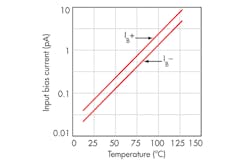
Pease’s response was more pointed: “No, it may be because of the amplifier’s Ib [input bias current]. You cannot make an integrator, and WISH it will never drift. That does not work. If the battery is +, then the charge-amp’s output will be MINUS V, and of course the integrator will integrate that. If you didn’t want it to do that, why did you connect it that way?”
Pease continued, “If the charge remains constant, the integrator will integrate the signal. You cannot ask the output not to integrate away. I think you have designed a system that will not work, because integrators will integrate. They can’t help that.”
As usual, Pease had to ask for more information, while giving a little barb to the computers that so bedeviled him: “If you can make a COMPLETE schematic of your signals and capacitors (with values), can you put that into a PDF attachment? My computer will usually let me see those. Send to this email address. EXPLAIN (text will be fine) what all the signals are doing, and their nominal sizes, and explain what you want to happen. Integrators and Charge-Amplifiers normally have to be re-set, or have a dc feedback resistor. (Or, the loop has to be closed in some way.)”
Then to try and drill home the advice, Pease once again noted, “If you want to make a charge-amp, you have to be able to do a re-set, on a sample basis. Otherwise, the amplifier will integrate its own errors and will drift off forever — as you are seeing. You can’t just ask for a better amplifier, because the LMC660 is the best in the world, at 3 fA of Ib.”
Back To The Lab
Note Pease’s plug for the LMC660 (Fig. 4). Pease was used to having customers blame National Semiconductor’s parts when the real problem was that they did not really understand the application or how real physical amplifiers worked. This was one of the reasons he disdained Spice simulations. The mathematically perfect models of some amplifiers do not represent the realities of a semiconductor device.
If you are going to use Spice, be sure that you have amplifier models that do represent the real parts. Linear Tech’s models are usually good since they also offer LTSpice, Analog Devices’ models are typically quite good, and the later models from Texas Instruments are also thorough. But not many models show what happens to power supply current when the output hits the rails or how long it takes to recover from that overload.
Amplifier guru Paul Grohe, who was Bob Pease’s protégé at National Semiconductor, admired the models for the now obsolete Comlinear parts. They were almost transistor-level models that would give away the internal IC design. I later met Mike Steffes, when he was at Intersil, who was previously the Comlinear application manager. He smiled when I mentioned how good those models were. I asked if he took grief from the IC designer because the models were so accurate.
Steffes said that there was some grumbling that he was unveiling design secrets, but there were two mitigating factors. One was the parts were made on AT&T’s ultra-high-speed process, which nobody else had access to. So, having the design tricks without the process was useless. The next factor was just good applications philosophy. “These were really high-performance parts, and I got tired of engineers not getting the right results off their Spice models,” Steffes told me. So, he created and released Spice models that designers could count on. Bravo.
Understanding a bit more about bias current can demonstrate some of these shortcomings. An op amp will make an inverted output, since you have to apply feedback to the minus pin, but that is not usually a problem. You can follow the integrator with an inverter, or you can set up the circuit as non-inverting and live with the common-mode problems, dc error, and range inaccuracy.
You might notice that the form of the integrator circuit resembles a low-pass filter. Indeed, you can think of a capacitor with no resistor across it as a low-pass filter with an infinite time constant. If you put a pulse into such a circuit, the output would represent the area under the pulse, and would never return to 0 V, unless you applied a negative voltage for a time and amplitude so the area under equaled the area of the positive pulse.
With a resistor across the capacitor, even one of megaohm magnitude, the output will eventually return to zero. An amplifier expert would say that you have given a dc return path to the feedback network.
That confused engineer who wrote Pease reminds me of some of my Harley mechanic friends. They say they routinely get calls where a customer will say “My engine is making a funny noise. What’s wrong?” So maybe it is typical that engineers wrote Pease with a complaint but never gave him enough information to understand what the problem really was. Despite Pease’s pointed questions and passionate response, he ended his e-mail to this engineer with the note, “Let me know what is going on, and WHAT you are trying to do, and I’ll try to fix it. Best regards. / rap”
Then, emphasize his point, Pease added a short story to his e-mail response: “P.S.: To make a long story short, a KING asked his WIZARD to make him invisible. The WIZARD did that. Good magic!! The next morning, the king was FURIOUS. ‘Get that lousy wizard up here!’ Trembling, the Wizard asked, ‘What is the matter, sire?’ The king roared, ‘I asked you to make me invisible, and I'm still bumping into things.’” Then Pease added a final note: “Be careful what you ask for; you might get it” (Fig. 5).
About the Author

Paul Rako
Creative Director
Paul Rako is a creative director for Rako Studios. After attending GMI (now Kettering University) and the University of Michigan, he worked as an auto engineer in Detroit. He moved to Silicon Valley to start an engineering consulting company. After his share of startups and contract work, he became an apps engineer at National Semiconductor and a marketing maven at Analog Devices and Atmel. He also had a five-year stint at EDN magazine on the analog beat. His interests include politics, philosophy, motorcycles, and making music and videos. He has six Harley Sportsters, a studio full of musical instruments, a complete laboratory, and a video set at Tranquility Base, his home office in Sun City Center Florida.
Comment About the Article
To join the conversation, and become an exclusive member of Electronic Design, create an account today!

Leaders relevant to this article: