Home or Very Small Office Electronic Circuit Prototypes, Part 4

This column will address reflow-oven temperature testing. It uses the lab equipment to build the circuit board designed in Part 1 and shown in bare PCB form in Part 3, adding further parts to assemble a four-channel digital-to-ac power-control module.
Reflow-Oven Temperature Testing
As mentioned near the end of Part 2 in Step 21, the actual board temperature must be verified to expect built boards to actually perform as designed. If the temperature is too low, solder joints may not even flow. Too high a temperature, and parts or boards may be damaged by excessive heat. This latter scenario is of greatest concern, since a weakened part may or may not behave in an obviously bad fashion. Analog circuitry may not perform in specification for no apparent reason, and digital circuitry also may not perform accordingly, such as memory parts having short retention spans. Worse, parts may fail early or be already failed, especially optoelectronic parts, when the circuit exits the oven.
The adhesive test discs received from McMaster-Carr 9246T27 (Part 2, step 21) were TMC Hallcrest 05CMCMRNG8F02PK, Thermax round 5-level clock irreversible temperature indicators. Research found these devices were rated ±1% of dot temperature in C + 1 degree.
I went through the first disc and found out the oven was further off than expected, and the second dot told me I needed to be careful with temperature steps. The third and fourth discs were stepped from 200°C through 23°0C with 1-degree steps; third disc on even degrees, fourth disc on odd degrees. The data gathered was collated and analyzed for when each disc dot activated (Table 1).
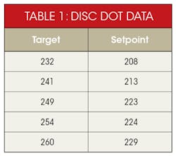
Analysis of that data resulted in an RMS slope of 0.7738, and intercept of 28.11°C. A table was generated for each 5 degrees of target temperature from 230°C to 260°C, and since the setting is integer-only, it resulted in Table 2.
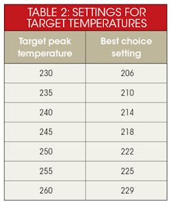
That data was also plotted to better observe the errors that might be expected for use of the best choice setting value:

Conclusions to be drawn from this testing:
1. The temperature of the thermocouple reading with the oven cold seems to be within about 5°C of actual.
2. The temperature of the oven during reflow is highly dynamic and the sensor isn’t thermally attached to the reflowed PCB.
3. The observed typical error between setpoint and label-measured peak temperature, from raw data, was 24 to 31 degrees, where board temperature was hotter than sensor temperature.
4. An overshoot of 2 to 3 degrees was observed in the thermocouple reading after the oven controller secured heaters on a reflow cycle.
5. The size of the setpoint to actual temperature error would mean a setting of 230°C. Typically, a minimal peak reflow temperature for tin-silver-copper lead-free solder that melts near 219°C would result in an actual temperature above 260°C, generally the maximum reflow temperature for surface-mount (SMT) components. Note that many SMT connectors and optoelectronic components are rated in the 240°C range.
This testing reaffirmed need for the classic mentor question: “Did you test that new piece of gear out before using it in the lab on deliverable hardware?”
Circuit-Board Paste Assembly, Reflow, and Hand-Soldering of Through-Hole Part
For this project, after trying unsuccessfully to get data converted to a form that the local maker shop could use to cut polyester or kapton film, I decided to use a small 3-ml syringe with a 22GA applicator tip to put paste on the pads. This is a bit slow and clumsy, but for a single board of such complexity, it’s not bad. The 3-ml syringe was chosen to reduce the force needed to eject the paste through the very small applicator tip. A 10-ml syringe would have required considerably more force, since the plunger force varies with the inside tube area of a syringe.
I put a small bead approximately diagonally across each pad to meter the solder amount. I then placed all surface-mount parts using tweezers. Tweezers that I normally use are sharp tip, bent tip (like digikey.com part EROP7SA-ND, but OLD). For big parts, I will use the rounded-tip flat tweezers (like digikey.com part EROP2ASA-ND).
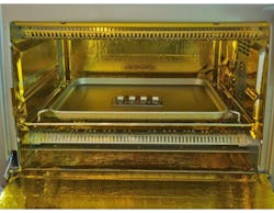
While doing the placement, I ran a warm-up cycle on the reflow oven built in Part 2. Figure 1 shows the SMT-placed PCB near the center of the tray in the oven just prior to the reflow cycle.
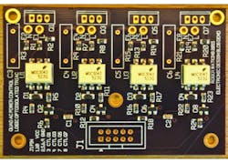
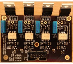
After the reflow cycle completed, I removed the PCB and inspected it. Figure 2 shows the SMT parts soldered to the PCB. The paste I used was Chipquik SMD4300SNL250T3, a water-washable flux lead-free paste purchased from Digi-Key (SMD4300SNL250T3-ND). I loaded into the syringe with a plastic knife, and tamped to eliminate bubbles. The oven was set for a peak temperature of 250°C due to the reflow profile rating of the optoisolators, the most restrictive part on the board. As is apparent on careful inspection of the figure, the paste nicely wetted all pads and component terminals, and I had no tombstoning of the chip parts.
To keep things lead-free, I soldered the through-hole parts to the board using Chipquik SMDSWLF.020, a no-clean, flux-core, lead-free solder wire purchased from Digi-Key (SMDSWLF.020 2OZ-ND). After the soldering was completed, I washed the board first in denatured alcohol, and after two flux-brush scrubbings, transferred the board to a distilled water final wash. This gets rid of almost all of the flux, allowing for better inspection, and adhesion of conformal coatings if used. I do this wash out of habit after having problems in the past with high-impedance amplifier circuits, compensation networks on switching power supplies, and RF circuit tuning variability, all of which ultimately were traced to board cleanliness issues.
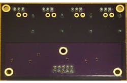
The cleaning evolution revealed that the Chipquik solder wire no-clean flux was not as soluble in ethanol as most other wire fluxes in my experience. The flux only softened and was removed mostly mechanically from the bottom of the board. Some un-removed residue is visible in Figure 3. Figure 4 shows the cleaned and completed board from the top side.
The completed board now needs to be wired and mounted on a heat sink. To ensure best performance, the heat sink chosen has a top flat surface, fins toward its bottom, and end-mounting for a fan to provide forced-air cooling. There are five mounting holes in the board. For my mounting, I actually only used the three toward the bottom of Figure 4 (bottom corners and center), which allowed for a little bit of flex for the holes and mounting to my heat sink.
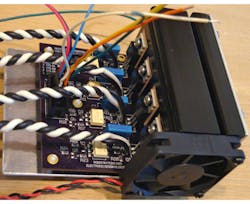
For testing, I installed 16AWG black/white twisted pairs to the E1/E2, E3/E4, E5/E6, and E7/E8 terminal pairs. I built up a test cable with connector to interface J1 (for a higher-production scheme, the pads of J1 might have wires soldered directly to them). The test-cable connector has a red/black 20AWG zip cord for power and discrete wires with blue, yellow, white, and orange wires for the four control signals and green for the control signal return. See Figure 5 for a photo of the board wired for test. Note that only three of the five board mounting holes were used, since the four TO-220 mounting screws do a pretty solid job of retaining the right side of the board.
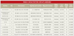
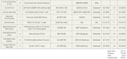
I have included the bill of materials (BOM) for this board (Table 3). Price-break quantities were what I purchased to be able to make two assemblies with spares for first-build and testing. Not included in the BOM are wire, the 10-position housing and crimp terminals for testing, the aluminum sheet metal used, the two sheet-metal screws used to hold the fan to the heat sink, and the four screws used to hold the aluminum sheet metal to the heat sink.
The black and white 16AWG wire and the 20AWG red/black zip cord were left over from the oven build. The blue, white, green, yellow, and orange wires were from spools in my very old stock of miscellaneous stuff from tinkering. The 0.062- × 6.0- × 2.0-in. sheet metal was left over from the oven build, bent so that 2.0 in. on the right in Figure 5 covers the heat sink’s fins in order to contain the air from the fan, and screwed to the heat sink at four points. The solder wire and paste, the flux pen, and the tools aren’t included in the BOM either, but are all pretty standard consumables and lab tools. I purchased the 10-position housing (Digi-Key WM9150-ND) and crimp terminals (Digi-Key WM2512-ND) for testing this circuit.
I’ve looked a little more into the solid-state relays provided by whizoo.com, which originally got me going on this design, and found that the Digi-Key and Mouser prices are somewhat high. On eBay, I found several entities selling relay modules that appear to match the Whizoo kit units as “Buy It Now” items for around $3.50 direct from China, and for under $5.00 from North American distribution.
These will operate for 3- to 32-V dc inputs and for 24- to 380-V ac outputs. However, they will require special drive circuitry for low-voltage logic circuitry.
One of the main reasons for creating the ControLeo design described in the Whizoo crowdfunding site was a need to interface with relays. The quad optoisolated ac control circuit may still be useful in terms of allowing a different control circuit to operate the oven—the circuit is readily adapted to control logic levels down to below 1.5 V dc simply through resistor adjustment. One possible candidate, having a QVGA LCD included, was the SW4STM32 from STMicroelectronics (Digi-Key part 497-13898-ND, $25.54) with a free development toolkit (AC6). As may be apparent, I’m fond of evaluation kits as they are distributed at near-cost to get engineers to develop quickly using the featured device. Such a scheme means that evaluation boards are often the most up-to-date and least expensive for such projects. Another alternative of recent importance are the Arduino series of boards—open design circuitry generally based on the Atmel microcontroller line that’s targeted at “makers” and home hobbyists with tight budgets.
In my next column, I expect to address use of my updated lab test equipment for verifying the AC Power Control assembly built as described. This will also include recommendations for those of us who don’t have a co-worker with CPR training present in or near our lab, but there’s a need to work on line voltage or higher.
About the Author
RWatkins
Consulting Engineer
Roger Watkins is an Ex-Navy Submarine Officer, having completed Submarine Officer and Submarine Nuclear Engineer qualifications. He has consulted, designed electronics, written software/firmware, searched patents, and managed design teams for several companies over many years, including:
- Analysis & Technology Inc. (acquired by Anteon International, today part of General Dynamics Information Technology)
- Lake Shore Inc. (today Oldenburg Group Inc., Defense)
- Caterpillar Inc.
- Quill & Disc Inc.
- Validus Technologies LLC
- bb7
- Intellihot Green Technologies
Comment About the Article
To join the conversation, and become an exclusive member of Electronic Design, create an account today!

Leaders relevant to this article: