
Large wind turbines are popping up across the land (see “Innovative Designs Keep Power Turbines Spinning” at http://electronicdesign.com/power/innovative-designs-keep-power-turbines-spinning). There is a tremendous amount of innovation in the blades and the rotor. There also is a huge amount of industrial design in the appearance of the machine.
They do look good—warm, inviting, and as green as a green bean casserole. The blades are designed for maximum power, minimum swept area, and likely minimal air disturbance near the tips. If the machine delivers maximum power at 19 rpm, and the radius of the blades is 147.5 feet, the velocity at the tip of the blade is then 293 feet/second at full power.
Related Articles
- Wind Turbines Play In Paradise, But Not In Falmouth
- Surge Suppression Upgrade Kits Fortify And Protect Turbine Equipment
- Take Back Half Convergence Algorithm Stabilizes Microhydro Turbine Controller
The big question then becomes what’s next. How can power electronics and machine innovation impact these wonderful machines? The yaw actuators, blade pitch actuators, and prime mover seem like fertile ground for improvement if we look at the rotating machines. They all have large gear reduction ratios that source (or sink in the case of the prime mover) very high torque. But I don’t think that’s grounds to simply swing the gavel of innovation and demand that all of these machines go toward high pole count, permanent magnet (PM) synchronous machines, or any other solution for that matter.
The Yaw And Blade Pitch Actuators
Perhaps a direct drive PM machine is heavier than the existing technology. That sounds okay on the ground. But 300 feet in the air when you’ve crawled into the rotor and are breaking loose the bolts on a blade pitch actuator, lowering something that weighs less than the 300-lb actuator to the ground would be a welcomed advantage (about 150 lb of motor, about 150 lb of gearhead). Lowering a heavier load may lead to a few more expletives. The yaw actuators are similar in proportionalthough slightly heavier.
For the lightweight solution we can give credence to the aviation industry, which has mastered generating high torque with minimal weight in actuator applications. The aviation industry does this with very high-speed machines, perhaps with a Ke corresponding to 10,000 rpm or higher at maximum driven amplitude. The fast, lightweight machine then ties to a gearhead that delivers proper reduction.
Both the yaw and blade pitch actuators could see innovations along these lines. The motor would become much lighter, and the gearbox would stay about the same or perhaps get slightly heavier. The net weight loss would be a positive attribute, in addition to offering a more efficient system than the prior technology. But the reliability doesn’t take that quantum leap forward. Torque is still multiplied by the output gearing, so the main failure mechanism is still in play.
The high-pole-count PM machine could certainly deliver more torque in these applications and be more reliable since it requires no gears, but the weight of the machine (often driven by the back metal needed to contain the flux) would be prohibitive. This is where the argument comes in that the high-pole-count PM machine needs no gears and thereby doesn’t share the primary failure mechanism of the gearhead motor. For the added weight of the back metal, the failure rate drops substantially, perhaps to near ideal. One technology could be easily debated over the other: lightweight versus high reliability. If the machines truly live up to the 30-year serviceable lifetime, perhaps the heaver solution will dominate.
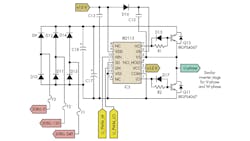
The electronics opportunities that we will see in these machines are very similar to the previous and present generations. There will be position encoders, related signal conditioning, robust control, and inverters to run these machines. IR makes a lot of insulated gate bipolar transistors (IGBTs) and drivers directly applicable to these requirements. One may consider the IRGPS4067 and IR2113 in these applications (Fig. 1).
The Mighty SSDFIG
On the main deck of the nacelle, there is an application that is absolutely ripe for innovation. The super-synchronous, doubly fed induction generator (SSDFIG) and the gearbox certainly get the job done. Some would argue that the input is free, so what’s a little loss in the gearbox and the rotating machine? But that’s not true based on the economics of maintenance and the statistics of failure. Rotating stuff wears and breaks. The SSDFIG and its mating gearbox have a lot of rotating parts. The wear on these rotating parts requires maintenance and downtime. Tribology certainly prolongs this process, with the added need to maintain the lubricants at proper temperature and purity. These things aren’t free.
We can’t discuss this in a vacuum. It must be pointed out several direct drive machines are deployed as prime movers in the wind industry. For reasons unknown, these machines are not prolific in the many large wind installations in the Midwest.
The problem seems to beg for direct drive, which doesn’t come easy. Can you imagine perhaps an instance where the machine makes full power at 19 rpm, but it must survive twice those speeds during heavy storm or tornado conditions should the brake and blade pitch actuator fail? That’s a plausible mode of operation, and the machine should certainly be designed to handle that. But what then of the physics?
If the machine has a Ke or back electromotive force (EMF) designed for optimal output voltage at 19 rpm, and the rotor speed doubles, the adverse condition voltage is then twice this amount. We could wave our hands and tell tales of field weakening and whatnot where we can blast some counter magnetomotive force (MMF) vector into the poles and actively reduce Ke (and Kt!), but there are practical limitations to this method—and what if the control was hit by lightning and no longer operable? That’s not likely, but it must be considered.
If we are to avoid the age-old idea of field weakening (first started to over-rev dc shunt motors), then we must design the insulation system of the rotating machine to handle these higher voltages and perhaps some damping elements to damp any nasty peaks on the over-revved, sub-optimal, high-voltage waveform. That’s pretty straightforward, although it may very well be unsavory in the added insulation cost. If we then complement this with a contactor in series with the rectifier stack to avoid overvoltage conditions on the dc link or the switches and a fail-safe power source to actuate the contactor, the system can survive these climatic nasties without fail.
As to the weights involved, if we opt for the direct drive solution and eliminate the main gearbox, the prime mover will no doubt get heavier based on having more poles and more back iron and being robust enough to directly handle those millions of foot pounds of torque. How much heavier remains to be seen, but in view of no longer needing the massive gearbox, perhaps it will be a net savings.
For a synchronous PM machine in these conditions, we have several opportunities for power electronics and controls. The rectifier stack and energy storage elements (perhaps a capacitor or battery bank) will need to be designed, as will the inverter and the control. There also needs to be a means to pre-regulate the dc link to provide fairly constant voltage to the inverter. The control must understand adverse conditions, the speed of the wind turbine and that correlation to output power, voltage and phasing of the feedpoint of the grid, and perhaps some active volt-ampere reactive (VAR) compensation. This is not a trivial design.
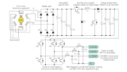
An understanding of line transients, machine transients, switchgear transients, ferro-resonance, and many other large-scale perturbations combined with the desired longevity of the machine will drive very rugged power switch and driver selection. I’d expect the power conversion stages to look a lot like that in an ac traction driven locomotive—massive IGBTs, massive rectifiers, perhaps with the added idea of energy storage to smooth delivery in changing winds (Fig. 2).
Fire Trucks And Wind Turbines?
Given the cost and scarcity of N52 neodymium iron boron PM magnets,It is further conceivable to derive a “non-PM” direct drive machine for the prime mover built along the lines of a “fire truck alternator.” The fire truck alternator uses no slip rings. It comprises two machines back to back in a common housing.
The smaller pilot machine has a pilot rotor that cuts dc flux in the pilot stator and generates ac current that is rectified and passed into the main rotor as dc current (excitation). The main stator then cuts this flux and produces ac current as the output. The rectifier is built into the rotor, so no slip rings are required. I refer to this as a “fire truck” alternator as a matter of memory. No slip rings allows for no sparks, which allows for no fire in the presence of combustible “stuff” as a fire truck may see.
Entropic memory tricks aside, this is a valid technique. It could further be improved by adding perhaps a centrifugal switch that cuts out the rectifier connection to the main rotor during an “all balls outward” windstorm. This would present a valid solution to de-energize the rotor (Ke goes to near zero) on overspeed conditions. Language police need not be offended. The phrase “all balls outward” directly relates to the flyball governors used in the early steam and internal combustion prime movers to describe the visually observable over-speed condition.
The control and power electronics required for this type of prime mover realization is similar to the PM synchronous machine with the augmentation of being able to directly control the field and power flow at any speed at the machine. The pilot machinecontrol may use an isolated dc-dc converter, perhaps a half bridge with resonant switching. The IRGP4067 is, again, a good robust choice of power switch for an application like this assuming excitation levels are within reach.
What’s Next?
This article simply scratches the surface of the large wind turbines of the future. It is a suggestion of what the wind turbines of the future may look like in view of what they are presently. Clearly there are complexities well beyond its scope.
My hope is that the wind industry will take advantage of the expertise on power conversion, rotating machines, controls, and monitoring that exists among us and realize some of these wonderful innovations to improve the machines, their maintenance requirements, and their failure modes. This will take a little investment, but the net result will be higher yield, longer time between service calls, and less down time.
I fall back to the ingrained old school field applications engineer stance—that of being ready, willing, and able to help identify, comprehend, and solve these problems. The power levels go a little beyond an afternoon proto-board whipped up on the bench, but I’ve become comfortable with that as well.
Paul Schimel is a senior applications engineer at International Rectifier. He has more than 17 years experience in power electronics design, EMC, and transformer design including offline ac-dc converters for medium and high power levels, motor drives, and dc-dc converters. He is a hands-on engineer and innovator, endlessly building power electronics circuitry, welding, and machining for alternative energy,HVAC, and propulsion applications. Also, he is a licensed Professional Engineer and holds two patents.
About the Author
Paul Schimel
Senior Field Applications Engineer
Paul Schimel is a senior field applications engineer at International Rectifier. He has more than 15 years experience in power electronics design, EMC, and transformer design including offline ac-dc converters for medium and high power levels, motor drives, and dc-dc converters. He is a hands-on engineer and innovator, endlessly building power electronics circuitry, welding, and machining for audio, HVAC, and propulsion applications. Also, he is a licensed Professional Engineer and holds two patents. He can be reached at [email protected].
Comment About the Article
To join the conversation, and become an exclusive member of Electronic Design, create an account today!

Leaders relevant to this article: