For The Best Receiver Testing, Record And Play Back Real-World Signals
The testing of any new wireless receiver design usually requires conventional test instruments such as a vector signal generator and appropriate output instruments like a scope, vector signal analyzer, or spectrum analyzer. But the result is only a partial test of what the receiver will actually do with real signals, since such testing won't account for noise, interference, and other conditions such as multipath and fading effects.
One solution is to perform "drive" tests, placing the receiver in a typical application's environment and evaluating its performance. Unfortunately, field tests are time consuming and expensive. Also, they can be painful. Fortunately, there is a better solution streaming real-world signals that have been recorded in the field.
Impairments In The Wireless Environment
Most wireless devices are made for mobile or portable service where the user and the radio may be in motion. Cell phones are the best example, but other products can be used in mobile settings too. Laptop computers with cell-phone PC cards, Wi-Fi wireless local-area network (WLAN) radios, and WiMAX radios are other instances where the radio could be in motion. GPS navigation receivers, satellite and HD radios, and the forthcoming mobile TV devices using the Digital Video Broadcast (DVB) or Media FLO standards require impairment testing as well.
The use of these devices in urban environments also introduces major obstacles and impairments. The most common impairments to a wireless signal are additive white Gaussian noise (AWGN), interference, and multipath fading. Any receiver test must account for all of these factors to ensure a reliable device.
Noise
Signal strength, usually measured as signal-to-noise ratio (SNR), can be problematic when a receiver is far from the transmitter. Such noise, often modeled as AWGN, is a mix of external noise and the noise contributed by the receiver front-end components. The overall SNR determines the reliability of the link. Signal strength can be improved with more transmit power, greater receiver sensitivity, or the addition of gain antennas. Overall, a high noise level will reduce the error vector magnitude (EVM) of the receiver.
The presence of noise will also determine factors such as data rate in wireless applications that use adaptive modulation schemes. With low noise, a 16QAM or 64QAM (quadrature amplitude modulation) signal will produce faster data rates.
As the noise increases, the symbols are scrambled, as a constellation plot will reveal. In some systems, this results in a change to quadrature phase-shift keying (QPSK) or even binary phase-shift keying (BPSK). This reduces the data rate but also makes the symbols easier to recover, creating a more reliable link.
Multipath Fading
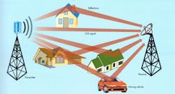
Multipath propagation is common in most UHF or microwave applications. In some cases, signals travel a direct line-of-sight (LOS) path from the transmit antenna to the receive antenna. However, nearby obstacles such as cars, buildings, trees, mountains, and even airplanes can reflect some of the signal (Fig. 1). The nature of the reflections can change according to the weather, temperature, and time of day.
Receivers with omnidirectional antennas are particularly prone to this impairment, because they receive reflections as well as the LOS signal. Multipath signals are delayed at different times with respect to the direct signal, so the receiver sees a combination of all the signals with different phases and amplitudes. The result is a cancellation effect that produces ongoing fluctuations.
Known as intersymbol interference (ISI), this effect increases the EVM of the signal. It also makes it more difficult for the receiver to establish carrier lock with the transmit signal. In applications where the predominant part of the signal is the LOS path, the amount of signal and the path robustness can be predicted using a Rician probability distribution.
In other applications, there is no dominant LOS signal, with the signal at the receiver coming from multiple reflections. For indoor operation, signals pass through walls, floors, or ceilings and are further reflected by furniture and people in motion. In such situations, the path loss and characteristics and signal strength are better predicted with a Rayleigh probability model. The Rayleigh model is commonly used when prototyping cellular receivers.
Adjacent Channel Interference
Interference will also affect the link reliability and the performance of the receiver. It can come from other signal sources on the same or closely adjacent frequencies, sources with misdirected antennas, illegal transmissions, spurious radiations caused by harmonics, or intermodulation products.
A receiver with good selectivity and low intermodulation products will perform best in the wireless environment because these products can appear in the bandwidth of interest. A good test for this is to add one or more continuous signals within or adjacent to the test signal. By observing a constellation plot with and without the interfering or blocking signals, you can determine the receiver's ability to reject such interference.
Note that government regulations limit adjacent channel interference, but they don't eliminate it. This receiver design typically incorporates filters to reduce this effect. Also, while the wireless standards account for these impairments, it is still difficult to create realistic test strategies that will validate or verify receiver performance.
Test Strategies
There are three primary techniques for testing: the generation of a "golden" signal, simulation with recreated disturbances, and real-world signals in the field.
You can use a vector signal generator to produce the ideal radio signal that complies with the wireless standard used. But a perfect signal won't indicate how the receiver will work in a field setting, especially with mobility. You can attenuate it, but that is as far as the impairment goes. This is useful for measuring sensitivity but insufficient for testing other characteristics.
Second, you can use the "golden" signal and add impairments to it. You can add noise and even other interfering or blocking wireless signals. Generating multipath impairments isn't easy. For certain types of wireless standards, signal-path emulation testers can emulate a typical environment, but they're expensive. Also, simulation alone is inadequate because simulations canâ??t emulate all of the impairments in a wireless channel.
The third option is to go out into the real world and put yourself into the kind of environment that will produce the signal variations that duplicate actual usage. Such driving tests are extremely time consuming and non-repeatable. In addition, drive testing creates the added challenge of creating a reproducible environment. This is problematic when performing design validation when it is important to correlate measurements between the revisions of a receiver.
RAID Records And Plays Back Wireless Signals
One increasingly common method of testing is going into the field and capturing real radio signals under actual conditions and recording them on a redundant array of independent (or inexpensive) disks (RAID). With "real world" test signals stored on the hard drives, you can then play them back in the lab for receiver testing.
By recording several examples of signals with different multipath and fading conditions, you can get a more realistic view of the receiver's performance under actual conditions. In addition, you can capture data from a variety of physical locations, enabling you to compare the environment of Munich with that of Tokyo.
While we regularly record audio and video data and play it back, we don't think in terms of recording RF signals because of the data throughput required to hold a sufficient test record. A modern vector signal analyzer with its maximum RAM capacity of several hundred megabytes limits the test signal length to only several seconds at most. But with todayâ??s modern PXI test instruments and a high-capacity RAID volume, you can use real-world signals up to several hours in length.
How It Works
A vector signal analyzer is set up as a receiver with an antenna at its input. This unit is taken into the field, and the received signals are downconverted to baseband by either a superheterodyne or directconversion process into I and Q signals. The I and Q signals are then sent to the RAID as digital baseband.
The RAID contains multiple highcapacity hard disk drives that record the digital IQ data. Acquiring 20 MHz of signal bandwidth requires a 25- Msample/s rate. With a data rate of 4 bytes per sample, the data throughput is 100 Mbytes/s. By using a 2 TB RAID unit, you can record up to five hours of test signals.
Recorded signals are then played back through a vector signal generator at the desired carrier frequency. This is the "golden" signal you use for testing. It provides a reliable method of receiver testing because the same signal can be used over and over again. In addition, the recording contains a more accurate view of the physical environment.
RAIDs make the recording and playback of RF signals practical and affordable. The RF test signals can be streamed to the receiver for hours. Figure 2 shows the typical equipment used for record and playback testing.
About the Author

Louis E. Frenzel
Click here to find more of Lou's articles on Electronic Design.


