This file type includes high resolution graphics and schematics.
With 97 networks launched in 2012 and 145 networks commercially “on air” today in 66 countries, LTE has achieved the fastest adoption rate ever for any mobile communication technology. Besides the new OFDM-based (orthogonal frequency division multiplexing) air interface and an all-IP-based (Internet protocol), simple, and flat core network architecture, LTE is the first cellular standard to take advantage of self-organizing network (SON) functionality.
Related Articles
- Use BCs And TCs To Improve LTE And LTE-A Infrastructure Timing
- Getting Ready For LTE-Advanced Design And Test
- An Introduction To LTE-Advanced: The Real 4G
One of the first SON features to be defined was automatic neighbor relation (ANR). ANR functionality is in high demand by network operators worldwide. Its aim is to significantly reduce the interaction of the service provider with its network during the manual process of managing neighbor cell relations. Over the past few years, this has become a challenging and time consuming task not only because of new technology deployments such as LTE, but also due to provisioning 2G (GSM, CDMA) and 3G (WCDMA, HSPA, 1xEV-DO) cells.
What’s My Name?
Before going into the details of ANR, it is important to get some clarity on the different but permanently assigned identities of an LTE basestation (enhanced Node B, eNode B, or eNB) during the network deployment process. The most obvious identity is the physical cell ID (PCI), which identifies a cell that is served by an eNB. The PCI is derived from the primary and secondary synchronization signal.
There are, in total, 504 unique PCIs being used throughout the entire LTE network. That relatively small number results in PCI reuse at some point, such as when the network is rolled out in a metropolitan area, not to mention the future plans of service providers worldwide to answer the forecasted capacity crunch with the deployment of small cells. The 3rd Generation Partnership Project (3GPP), the standardization body behind LTE, has specified additional identities to retain the ability to uniquely identify an eNB (and its associated cells) in an operator’s LTE network.
The first is a cell identifier, better known as an E-UTRAN cell identifier (ECI), broadcast with System Information Block Type 1 (SIB Type 1). The ECI, a 28-bit value, unambiguously identifies a radio cell within a public land mobile network (PLMN). The mobile country code (MCC) and mobile network code (MNC) form the PLMN identity.
In the U.S., one of the used country codes, for example, is 311. Two major carriers use the 311 MCC to identify their 4G LTE networks. The MNC is, of course, unique to each carrier and all other service providers. The PLMN and ECI form the E-UTRAN cell global identifier, or ECGI, which can be up to 52 bits long. While the PCI is supposed to be reused, the ECGI is a system-level parameter that must be unique.
All these identities—PCI, ECI, and ECGI—play an important role in the definition and execution of ANR functionality, as specified by 3GPP as part of Release 8 for all relevant technical specifications.
Network Operators Demand ANR
SON functionality is generally divided into three categories: self-configuration, self-optimization, and self-healing. ANR belongs to self-configuration. It relies on the device’s (user equipment, or UE) capability to report cells that it has detected but are not part of the neighbor list.
What we are calling a neighbor list is actually information acquired while reading system information in the form of SIBs. For LTE, these SIBs are primarily Type 4 and 5. Other SIBs provide neighbor list information for legacy radio access technologies, short RAT. SIB Type 4 lists the LTE intra-frequency neighbor cells—cells on the same carrier frequency, but with a different cell identity. SIB Type 5 provides neighboring LTE cells on a different frequency band (inter-frequency).
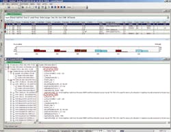
The SIB Type 5 inter-frequency list (recorded during network optimization measurements with the R&S ROMES drive test software) in Figure 1 shows two neighboring cells.
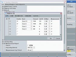
Their downlink frequency is highlighted in red. First, there is a neighbor on channel number (EARFCN) 6400 that corresponds to 800 MHz, which is frequency band 20 used in Europe. The second cell on EARFCN 3050 is at 2.6 GHz, corresponding to frequency band 7. This network operator uses three frequency bands for its LTE deployment. The decoded information, captured from a real network, can now be used in the lab for cell reselection tests on LTE-capable devices. The R&S CMW500 Wideband Radio Communication Tester can be used for this type of testing, where neighbor list and all other relevant parameter can be easily configured (Fig. 2).
Traditionally, the initial list of cells provided by SIBs 4 and 5 are based on simulations performed with network planning tools. The coverage prediction models used by these software tools by nature simulate real-life conditions and therefore leave room for error, as conditions and the environment may change. However, a missing neighbor in the neighbor relation table (NRT) is a common reason for call and connection drops due to failed handovers. Handovers are network controlled—that is, the network decides about the target cell. An up-to-date NRT is therefore essential for successful handover.
Carriers are required to perform drive tests to optimize neighbor lists manually for all technologies during the operational phase of a network. With the anticipated massive deployment of small cells, including picocells and femtocells, as part of heterogeneous networks (HetNets), this task will become even more challenging if not impossible. An automated way to determine neighbor relations is absolutely essential from an operational point of view, especially for LTE and LTE-Advanced.
ANR Procedure And Device Support
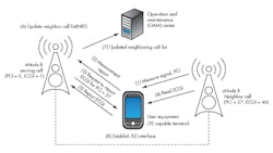
In the general ANR procedure, the eNB instructs the LTE terminal to take quality measurements of neighboring cells on a periodic basis—on the same frequency, for instance (Fig. 3). While doing so, the device may detect a PCI that is not listed in the neighbor list. When sending the measurement report to the network, the device uses the cell identity to indicate the cell it is reporting, including the newly detected cell with a PCI of 27.
After receiving the measurement report, the eNB instructs the terminal to report the ECGI, while reading the BCCH of that cell. In the next step, the UE reports the example ECGI of 46, which the eNB will use to update its neighbor relation table (NRT). This table contains for each cell the neighbor relation (NR), determined by the target cell identifier (TCI), which comprises ECGI and PCI.
For each TCI, three attributes will be set: no remove, no handover, and no X2. The first stipulates that the eNB shall not remove this cell from the NRT. The second stipulates that no handover shall be initiated to this cell, whereas attribute three excludes the establishment of the logical X2 interface to this identified cell and its serving eNB. The operation and maintenance (OAM) center controls the listed attributes. It is the only authority that can delete entries from the NRT.
As indicated earlier, ANR enables intra-frequency and inter-frequency neighbor cell detection for LTE. For the latter, the network needs to inform the device about which frequencies to measure. It also requires the scheduling of measurement gaps, which enables the terminal to retune its receiver to the instructed frequencies and take the required signal quality measurements.
Feature group indicators (FGIs) indicate ANR support. The FGI for LTE as of 3GPP Release 8 is a 32-bit map, where each bit indicates the device’s support of a specific feature. This bitmap is submitted to the network during the initial registration and attach procedure as part of the UE capability transfer.
This file type includes high resolution graphics and schematics.
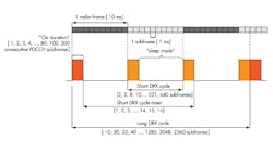
The FGI bits of interest are bits 5, 17, 18, and 19. Bit 5 defines the support of the long discontinuous reception (DRX) cycle. DRX saves battery power by not continuously monitoring relevant downlink channels. The device transitions into a kind of “sleep mode” and only wakes after certain periods to read the physical downlink control channel (PDCCH).
The DRX cycle generally consists of an “on duration” and a sleep period (Fig. 4). Both periods are under network control as maintained by the basestation and are configurable via several parameters and timers. An LTE-capable device always switches first to a short DRX cycle. If no data is sent during this period, the terminal will move to the long DRX cycle. For ANR, the “sleeping mode” may be used to retune the receiver to take, for instance, intra- or inter-frequency measurements for LTE or even for other RATs.
So why is the long DRX cycle so important and required for ANR? As described earlier, after the device reports the newly detected PCI, the network also will instruct it to report its ECGI. As previously noted, the ECGI consists of the ECI and the PLMN identity. Both IDs are transmitted within SIB Type 1, which has a fixed periodicity in LTE of 80 ms. Standard measurement gaps do not provide enough time to successfully detect and decode SIB Type 1 for the newly detected cell. Only the long DRX cycle permits the device to derive the PLMN identity as well as the ECI, enabling the ECGI report back to the network.
Finally, bits 17 to 19 determine if the device can perform periodical measurements for intra-LTE (intra- and inter-frequency; bit 17, 18) or for inter-RAT (bit 19), i.e., 3G/WCDMA.
Quality Measurements And Event Trigger
Devices should not scan for neighbors continuously in the hope of finding a cell that’s not part of the neighbor list. The ANR procedure is well embedded within the overall quality measurements that a device would take independent of ANR. These quality measurements are based on conditions set for the LTE network that trigger certain actions. The relevant receive-signal quality measurements for LTE, which the mobile device takes, are reference signal received power (RSRP) and reference signal received quality (RSRQ).
RSRP is the average power level over all subcarriers within the signal bandwidth that carry the reference signal pattern, excluding noise and interference. A 10-MHz LTE signal, for example, consists of 600 subcarriers due to a subcarrier spacing of 15 kHz. Every sixth subcarrier (100 subcarriers in total) carries a reference symbol out of the reference signal pattern. Reference signals are used for detection and coherent demodulation by the receiver terminals and also for the quality measurements mentioned earlier.
RSRP is measured in idle as well as in connected mode, i.e., during both a passive and an active connection with the network. In contrast, RSRQ is only measured in connected mode. In legacy technologies such as GSM, WCDMA, or CDMA20001xRTT, this metric would refer to the received signal strength indicator (RSSI). In fact, RSRQ is the ratio of RSRP over RSSI, impacted by the measurement bandwidth. Therefore, it is a quality measurement that accounts for all types of interference and noise that is degrading the received signal.
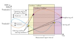
The reporting of these two quality measurements is event driven. Once certain thresholds are met or exceeded, the device starts measuring and reporting. Based on the measurement report, the basestation makes its mobility decisions. There are several event triggers for LTE-only, and there are others relating to inter-RAT to expedite handovers to legacy technologies.
Events B1 and B2 are used for inter-RAT. Events A3 and A5 are the most important for LTE and ANR. Event A3 is defined so a neighbor cell becomes better than an offset relative to the serving cell. Event A5, which is more complex, requires two criteria to be fulfilled (Fig. 5). First, the serving cell needs to fall below a certain threshold. Second, the neighboring cell needs to exceed another threshold. These thresholds are based on RSRP or RSRQ.
A network operator can set its event criteria on a parameter that provides more coverage and sensitivity (RSRP) or on a parameter for interference and noise handling criteria (RSRQ). This could be different from cell to cell. For RSRP, the value is within a range of 0 to 97. Whatever value is set in the information element provided by higher layers to the device, this value minus –140 dBm/15 kHz defines the actual threshold. If RSRQ is selected as the determining threshold, the range is 0 to 34. Whatever value has been defined, this value minus 40 and divided by 2 in dB defines the actual threshold.
Testing ANR On A Wireless Device
The testing of ANR functionality requires a basestation emulator, such as the R&S CMW500 Wideband Radio Communication Tester from Rohde & Schwarz, that can simulate several radio cells, e.g., for LTE and additional RATs, such as 3G/WCDMA. More complex ANR test scenarios require the simulation of multiple cells of different RATs, all in parallel. The R&S CMW500 also supports this simulation with the so-called Multi-CMW Setup. To test under more realistic conditions, including fading, an R&S AMU200A Baseband Signal Generator and Fading Simulator should be added to the setup.
A network operator’s ANR test strategy greatly depends on its LTE network configuration. Does the network operator use just one or multiple frequency bands for LTE? What are the supported legacy technologies for 3G? For simplicity, let’s assume the LTE network utilizes two frequency bands and not concern ourselves about which legacy technologies our virtual network operator uses.
In our example, the service provider shall use a low and high band combination for LTE, where the lower frequency band, 800 MHz for example, is used to provide coverage and smaller cells use the higher frequencies (e.g., at 2 GHz) to increase capacity in hotspot areas. To verify ANR support on a mobile terminal, a radio communication tester such as the R&S CMW500 can simulate a LTE cell in the lower frequency band, where the mobile registers attach to the cell.
During the establishment of the EPS default bearer, the terminal provides its capabilities as part of the UE capability transfer procedure, including the FGI. The test set has to check to see if bits 5, 17, and 18 are set to 1. As discussed above, these bits are required to perform intra-frequency and inter-frequency ANR measurements.
By sending an RRC connection reconfiguration message, the instrument configures the device to perform ANR measurements. It could use event A3 as trigger point, where the trigger threshold is set to be based on RSRP, for instance. The test set waits for the device to acknowledge this by receiving the RRC connection reconfiguration-complete message.
Next, the same basestation emulator would enable a second cell within the same frequency band but with a different cell identity (PCI). This PCI is not part of the actual neighbor list being provided to the device by system information. The reference signal power set for this cell must meet or exceed the A3 trigger event threshold. The device under test (DUT) is expected to report this cell identity to the tester.
Based on the reported new PCI, the instrument would have to configure the DUT to provide a measurement report for this cell while again using the RRC connection reconfiguration message that includes the cell to be measured, its frequency, the report quantity, and interval. While the DUT acknowledges this reconfiguration, the tester will verify in the next step the correct reporting, which may also include the cell’s ECGI. This ends the first part of the example test case, which is verifying intra-frequency ANR measurements.
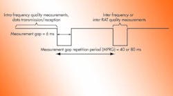
For the second part of our test scenario, we reconfigure the DUT to take inter-frequency ANR measurements. Therefore, an LTE cell needs to be emulated on a different frequency band, i.e., at the previously mentioned 2 GHz. The trigger event for this cell shall be A5 and the threshold is based on RSRQ, instead of RSRP. As the device has to retune its receiver to take quality measurements, measurement gaps have to be defined, including one of the two possible measurement gap repetition periods (MGRPs) (Fig. 6).
The DUT is now expected to report the identity of this new cell and, while reconfiguring the device to take periodic quality measurement on this cell, the identity of the ECGI within the next measurement report. At the end of this test scenario, the radio communication tester would have to release the connection and transfer the device back into idle mode.
Running such a simple test case would be possible with a correspondingly configured R&S CMW500 Wideband Radio Communication Tester. To test under realistic conditions, the RF signal has to be faded while running the test case. This can be done with the R&S AMU200A Baseband Signal Generator and Fading Simulator.
The test will produce a log file, which is displayed with the Message Analyzer, a software tool provided by Rohde & Schwarz used for protocol test case analysis and debugging (Fig. 7). The measurement report from the DUT reports the ECGI for the detected cell while performing intra-frequency ANR measurements.
3GPP has defined a number of test cases that directly or indirectly test ANR functionality. These test cases are defined in section 8.3.3 and 8.7 of 3GPP Technical Specification (TS) 36.523 Part 1 for UE Protocol Conformance. In addition, several network operators worldwide define their own test scenarios, similar to the one described above, to verify ANR functionality on devices intended for their LTE networks.
Summary
ANR is the first SON feature utilized in today’s LTE networks. With the planned upgrading of these networks toward LTE-Advanced and HetNets, it will become even more important as thedeployment scenarios use a mix of macrocells, picocells, femtocells, and relays to overcome forecasted capacity demands.
References
1. 3GPP TS 32.511 Telecommunication management; Automatic Neighbor Relation (ANR) management; Concepts and requirements [V11.2.0, September 2012]
2. 3GPP TS 36.300 Evolved Universal Terrestrial Radio Access (E-UTRA) and Evolved Universal Terrestrial Radio Access Network (E-UTRAN); Overall description; Stage 2
[V11.2.0, June 2012]
3. 3GPP TS 36.331 Evolved Universal Terrestrial Radio Access (E-UTRA); Radio Resource Control (RRC) protocol specification [V10.5.0, March 2012]
4. 3GPP TS 36.523-1 Evolved Universal Terrestrial Radio Access (E-UTRA) and Evolved Packet Core (EPC); User Equipment (UE) conformance specification; Part 1: Protocol conformance specification [V11.0.0, September 2012]
5. LTE Self-Organizing Networks (SON), Seppo Hämäläinen, Henning Sanneck, Chinzia Sartori, Wiley 2012
This file type includes high resolution graphics and schematics.
