Simple Tester Provides Readout of Crystal Frequency
Although oscillators are critical components in most electronic devices, designers needn’t design oscillators themselves in most cases, because the device contains a great deal of the oscillator circuitry. Instead, they only have to select the crystal and external capacitors needed for the oscillator function. If an incorrect crystal or external capacitors are selected, it can lead to a device that doesn’t operate properly, fails prematurely, or will not operate over the intended temperature range.
This file type includes high resolution graphics and schematics when applicable.
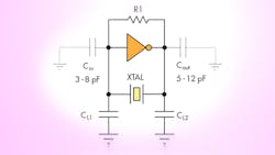
Quartz crystals have parallel and series modes of resonance, and an oscillator circuit is calibrated for one mode or the other, but not both. The common Pierce-gate oscillator (Fig. 1) uses a parallel crystal mode. Here, the crystal is specified by the frequency and the load capacitance (CL), which is the capacitance that the crystal needs to see to oscillate at the desired frequency. Phase-locked loops (PLLs) are commonly used to obtain inexpensive, high-frequency clock signals from low-frequency signals generated by oscillator circuits like the one shown, which mitigates the use of very-high-frequency crystals.
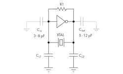
Designers must select the value of capacitors CL1 and CL2 to match the specified crystal load capacitance (CL). The most common mistake is to assume that the value of CL1 and CL2 in parallel is equal to the value of the CL, which isn’t accurate. This is because most designers neglect the internal input and output capacitances of the inverter gate (see CIN and COUT) and some other parasitic capacitances. These capacitances are significant in value compared to the external ones (CL1 and CL2); therefore, designers must calculate values CL1 and CL2 to match the CL as specified by the manufacturer using Equation 1:
[CL1 +CIN)(CL2 + COUT)/CL1 + CIN + CL2 + COUT] + CSTRAY = CL (1)
If CIN and COUT aren’t specified, then assume each to be 5 pF and CSTRAY to be 3 pF, as a starting-point rule of thumb. The oscillator circuit must be optimized by changing the starting values of CL1 and CL2 to get a total capacitance equal to CL specified by the crystal manufacturer. A trimmer capacitor can be substituted for CL1 and/or CL2 in order to manually tune their value. (Be sure to use ceramic capacitors with a low temperature coefficient (COG or NP0 types) for CL1 and CL2, and avoid capacitors made from Z5U material.)
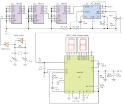
Figure 2 shows the schematic of a circuit that provides the frequency (in megahertz) of a crystal connected to terminals X1 and X2. That circuit uses a Pierce-gate oscillator configured for parallel resonance (U1). Its output goes through an unbuffered inverter (U3), to a series of four-bit synchronous counters (U4, U5, U6) functioning as a frequency divider, and then to a frequency-to-voltage converter (U7), to generate a voltage proportional to the signal frequency as generated by the oscillator. This voltage is digitized by the 3 1/2-digit analog-to-digital converter with internal seven-segment drivers (U8) to display the frequency of the crystal via a two-digit LED readout.
The user needs to make two adjustments to the circuit before it can be used:
• Adjust potentiometer POT2 to obtain VREF = VREF Hi – VREF Lo = 0.1 V
• Adjust potentiometer POT1 to obtain the voltage VAUX a little higher than 10 α mV for a crystal of fOSC = α MHz. Thus, for a crystal of fOSC = 4 MHz, voltage VAUX must be approximately 42 mV.
After making the adjustments, calculate the value of the capacitors CL1 and CL2 to measure the frequency of a crystal, using Equation 1; assume that CIN and COUT each equal 7 pF, CSTRAY is approximately 3 pF, and CL1 = CL2.
This file type includes high resolution graphics and schematics when applicable.
Jose B. Castro-Miguens, design engineer at Cesinel Co. for power electronics, instrumentation engineering, signal processing, and electric power control, received an electrical and electronic engineering degree from UPCO University, Madrid, Spain. He can be reached at [email protected].
Carlos Castro-Miguens, associate professor in the Electronics Department at Vigo University, Spain, received an electronic engineering degree from Vigo University. His primary research interests are in power electronics (dynamic modelling and control of power converters, design of magnetic components for powerconverters) and design of embedded systems.
References:
AN588, "PICmicro™ Microcontroller Oscillator Design Guide," Microchip Technology Inc.
"Pierce-gate oscillator crystal load calculation," Ramon Cerda (Crystek), RF Design, July 2004.
"Quartz Crystal Design Notes," Fox Electronics.
About the Author
Comment About the Article
To join the conversation, and become an exclusive member of Electronic Design, create an account today!

Leaders relevant to this article: