The RF signal analyzer is one of the most versatile tools on the RF test bench, allowing engineers to measure signals ranging from electromagnetic emissions to wireless communications. Most frequently, engineers use RF signal analyzers in spectrum mode to visualize the power profile of a signal or signals versus frequency.
However, one of the most useful features of a signal analyzer is its “zero span” mode, where power is displayed as a function of time. Today, the increasing instantaneous bandwidths of modern signal analyzers combined with the use of more advanced triggering modes has increased the usefulness of zero span measurements.
Inside an Old-School RF Signal Analyzer
Zero span mode certainly isn’t a new feature to spectrum analyzers. Engineers have been using it for decades to measure characteristics such as AM modulation and power in a specific bandwidth. To understand this feature, it’s worth explaining how zero span has been historically implemented and how to interpret the display and settings.
This file type includes high resolution graphics and schematics when applicable.
In the old days, a spectrum analyzer displayed power versus frequency by sweeping a local oscillator (LO) so the RF signal would pass through an analog resolution bandwidth (RBW) filter. In essence, the spectrum display was simply a series of power measurements measured over a range of frequencies.
We can glean a few important characteristics from the method by which spectrum analyzers historically produced their display (Fig. 1). First, note that by nature of the LO sweeping through the band of interest, the instrument determines each spectral line (a power measurement) at different points in time. !
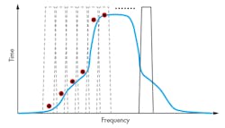
Second, the power measured at each point is fundamentally determined by the characteristics of the analog resolution bandwidth (RBW) filter. When measuring the instrument’s noise floor, a narrowband filter (i.e., a narrow resolution bandwidth) will result in lower power in each bin and a wideband filter will result in higher integrated power. Note that for this reason, signal analyzer noise floor is represented in dBm/Hz to account for the integration bandwidth.
To use an RF signal analyzer in “zero span” mode, one simply enters “0 Hz” as the span. On a traditional spectrum analyzer, the instrument would stop sweeping the LO and the analog resolution bandwidth filter would essentially be “parked” at a fixed frequency. Then, instead of displaying power as a function of frequency, the instrument would display power (through the integrated bandwidth of the filter) as a function of time.
Uses for Zero Span Mode
The ability to perform what is effectively a “power in band” measurement as a function of time has several important uses. In fact, long before today’s digitally architected modern signal analyzers, engineers frequently used zero span mode to measure the channel power of digitally modulated signals.
For example, the GSM cellular communication standard still specifies that the output RF spectrum (ORFS) measurement be performed using zero span mode. Although this measurement is essentially an adjacent channel power measurement (more literally, a series of channel power measurements at specific frequency offsets), the GSM standard was written well before the days of modern spectrum analyzers.
As a result, one measures power in an adjacent band by centering the spectrum analyzer onto the adjacent band and configuring it in zero span mode. In this scenario, the bandwidth of the RBW filter determines the bandwidth of the “power in band” measurement.
Resolution Bandwidth
Today, modern signal analyzers implement zero span mode digitally rather than with analog RBW filters. Although the implementation is different, our understanding of the historical implementation helps to better understand one of the most important settings: resolution bandwidth.
I’ve found that engineers are often confused with the meaning of the term “resolution bandwidth” as it relates to zero span measurements. When using a signal analyzer in traditional spectrum mode, the RBW is almost always set to a value that is substantially lower than the span.
For example, when measuring the adjacent channel power of a UMTS (WCDMA) signal, the span must be at least 15 MHz with a 30-kHz resolution bandwidth (per the 3GPP specifications). In this case, the resolution bandwidth does not determine the instrument’s instantaneous bandwidth but merely affects how the signal is displayed.
In zero span mode, the resolution bandwidth directly affects the effective instantaneous bandwidth of the measurement. Here, one can imagine that the spectrum analyzer is zooming into a single spectral line with the resulting power displayed as a function of time.
Because RBW determines the bandwidth of spectrum included in the power measurement, the configured RBW must generally be wider than the band of interest for the displayed signal to be useful. Note that the resolution bandwidth obviously never can be wider than the instrument’s instantaneous bandwidth.
Configuring Triggers Using Zero Span Mode
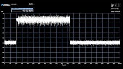
One of the most common applications for using zero span mode is to use it to configure trigger levels on a gated spectrum measurement. For example, in a typical 802.11ac transmission, the signal may only be present for a few hundred microseconds with relatively long periods of time between bursts. In this scenario, analyzing the spectrum requires one to configure a power trigger to time-gate the spectrum display.
When configuring a triggered spectrum acquisition, zero span mode can be a useful tool to determine the appropriate trigger level in addition to signal characteristics such as the duration of the pulse. A trigger level of –20 dBm is substantially lower than the average power of the packet payload (Fig. 2). This trigger level, combined with a minimum wait time of 1 ms, allows the signal analyzer to trigger on the burst both in the time and in the frequency domain.
Pulsed Power Measurements
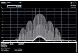
In addition to being a useful troubleshooting tool, zero span mode can be extremely useful for taking pulsed power measurements. Suppose one were to visualize a “power versus time” display of a radar pulse. In this scenario, the nature of a pulse transitioning from off to on creates sidelobes that are clearly visible in the frequency domain, especially with a triggered spectrum acquisition. A rectangular CW pulse appears as a sinc function in the frequency domain.
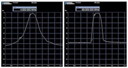
As Figure 3 illustrates, 95% of the pulse power is contained in approximately 2.4 MHz of bandwidth. (The bandwidth of the main lobe is approximately 4 MHz wide.) However, additional power is present in the side lobes. When analyzing this signal using zero span mode, one can imagine that 95% of the power can be captured in zero span mode by setting a 2.4-MHz resolution bandwidth.
To analyze the true characteristics of the pulse, though, it is important to capture as many of the pulse’s side lobes as possible. A higher-resolution bandwidth results in the ability to more accurately measure pulse characteristics such as rise time and fall time (Fig. 4).
As a general rule of thumb, pulse measurements require one to use a resolution bandwidth that is three to five times the 3-dB signal bandwidth to accurately measure characteristics such as rise time. However, especially for longer pulses, one can measure characteristics such as power by capturing only the main lobe in a narrower resolution bandwidth.
Conclusion
Although the implementation of this feature has changed over the years, zero span mode remains an incredibly useful capability of today’s RF signal analyzers. In fact, with careful attention to an instrument’s resolution bandwidth, one can perform a range of measurements including power, power-in-band, and even rise and fall times.
David A. Hall is a senior product marketing manager at National Instruments, where he is responsible for RF and wireless test hardware and software products. His job functions include educating customers on RF test techniques, product management, and developing product demos. His areas of expertise include instrumentation architecture, digital signal processing, and test techniques for cellular and wireless connectivity devices. He holds a bachelor of science degree with honors in computer engineering from Penn State University.
About the Author
David Hall
Head of Semiconductor Marketing
David A. Hall is the head of semiconductor marketing at NI and is responsible for developing and executing go-to-market plans for the semiconductor industry. His job functions include managing the semiconductor test business, identifying industry trends, and educating customers on best semiconductor test practices. Hall’s areas of expertise include ATE architectures, RF measurement techniques, digital signal processing, and best measurement practices for mobile and wireless connectivity devices.
With nearly 15 years of experience at NI, Hall has served in multiple roles throughout his career including applications engineering, product management, and product marketing for automated test and RF instruments. He has also held management positions in product marketing, which focused on employee development and meeting business results across products and application areas. Hall is a known expert on subjects such as 5G, the Internet of Things (IoT), autonomous vehicles, and software-defined instrumentation. He holds a Bachelor’s with honors in computer engineering from Penn State University.
Comment About the Article
To join the conversation, and become an exclusive member of Electronic Design, create an account today!

Leaders relevant to this article: