Zone Triggering Demystifies Scope Glitches
Oscilloscope vendors generally overcome the challenges of ever-greater signal complexity in many of today’s digital designs by keeping pace with advances in overall technology. For example, the newest oscilloscopes incorporate advanced parametric-based triggering, such as pulse-width triggering, rise/fall-time triggering, setup-and-hold-time triggering, and serial bus protocol modes.
Even with those triggering options, though, customer feedback suggests that many of today’s engineers and technicians avoid using some of them and stick with the old tried-and-true edge-based triggering. The feedback also indicates that engineers don’t use some of the advanced trigger modes primarily because of unfamiliarity and ease-of-use issues.
Explaining the details of all those trigger modes would take many pages. However, there’s another new—and easier—way to trigger on complex and infrequent signal anomalies: zone triggering. It’s best explained by comparing parametric-based triggering with zone-based triggering via examples of isolating random and infrequent signal anomalies.
Triggering Basics
Essentially, oscilloscopes take continuous pictures (real-time acquisitions) of electrical phenomena (signals) and then display/graph them as continuously updated voltage-versus-time waveforms. The challenge when capturing repetitive signals is that the picture-taking process of the scope must be synchronized to the input signal under test. Otherwise, the scope would display just a blur of superimposed, unsynchronized waveforms.
Since the earliest days of oscilloscopes with calibrated timebases, all have been able to trigger on signal edge crossings—either on positive-going (rising) or negative-going (falling) edge transitions at a user-defined threshold (traditionally called the trigger level). For decades, this has been the most commonly used oscilloscope trigger mode.
If the scope user attempts to observe simple and repetitive waveforms, such as a digital clock or sine waves, edge triggering works perfectly fine. However, if the user tries to view a complex digital pulse stream of data or desires to synchronize to an infrequently occurring signal anomaly, one that may be buried within a digital pulse stream (e.g., a glitch), simple edge triggering can be very limiting. Dealing with those situations is what has led to the multiple trigger types available in the latest scopes.
This file type includes high resolution graphics and schematics when applicable.
Triggering on “Runts”
Consider the example of a scope using edge trigger to display a digital pulse stream of data that contains occasional positive and negative “runt” pulses (Fig. 1). Runt pulses are digital pulses that don’t reach their intended high or low logic levels. Setting up the scope to trigger on only runt pulses, rather than on just any edge crossing, would likely help find the root cause of the errant logic-level pulses. That’s why most of today’s mid-range and higher-performance oscilloscopes incorporate parametric-based trigger modes, including “Runt trigger” and “Zone” trigger.”
Runt Trigger
Although the documented procedure of how to set up parametric Runt triggering is based on using Keysight’s InfiniiVision 3000T X-Series oscilloscope, the process is very similar for other vendor’s oscilloscopes. The step-by-step Runt trigger process is as follows:
1. Select the trigger menu that shows the available trigger modes.
2. Select the Runt trigger mode.
3. Establish a lower-level threshold that defines the maximum low-logic level.
4. Establish an upper-level threshold that defines the minimum high-logic level.
5. Select whether to trigger on either positive runts, negative runts, or runts of either polarity.
Figure 2 shows the scope triggering on positive runts using the above procedure. However, by examining the display for repetitive acquisitions, it is possible to see that the scope has actually triggered on two different runts, one narrower than the other.
If someone using this setup wanted the scope to trigger uniquely on only one of the runts, it would be necessary to further qualify the trigger condition by entering a timing qualification to isolate either the narrower or wider positive runt pulse.
Zone Trigger
To achieve the same results using the same scope’s Zone trigger mode, the setup procedure is:
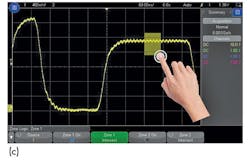
1. Draw a box (or zone) with the scope’s touchscreen (or mouse) to delimit the area of the infrequent wider positive runt.
2. Select “must intersect.”
With that setup, the scope synchronizes solely on repetitive occurrences of the wider positive runt pulse (Fig. 3). As long as the scope’s waveform update rate is fast enough to show a random and/or infrequent event simply by using conventional edge triggering, then Zone trigger can synchronize on it. Zone trigger makes it much easier and more intuitive to set up than any of the recently available advanced parametric trigger modes. For the engineer using the scope, it’s basically as easy as touching what to trigger on. When the trigger condition is met, it’s captured by the scope.
Triggering on a Non-Monotonic Edge
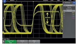
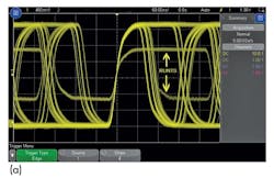
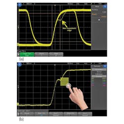
Another triggering challenge involves a signal with an infrequent non-monotonic edge (Fig. 4a). Such signals usually exhibit a normal/continuous rising edge. Sometimes, though, the rising edge experiences a momentary stall, and then continues rising to its final high logic level. A signal with this type of infrequent non-monotonic edge may appear as a “ghost” waveform if the scope’s waveform uprate is fast enough to show it.
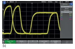
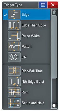
Uniquely triggering on just the signal that exhibits non-monotonicity requires that engineers first select what they deem the most appropriate trigger mode among the scope’s parametric-based modes (Fig. 4b). A really experienced scope user would likely know that the Rise/Fall Time trigger mode is the best option.
However, for many oscilloscope users, determining the appropriate trigger-mode selection could turn into more of a guessing game. Even if the user knows which mode to select, setting up all of the qualification parameters correctly could turn out to be more trouble than it’s worth. To illustrate, triggering on a non-monotonic edge using the Rise/Fall Time trigger mode includes the following setup steps:
1. Measure or estimate the rise time of “normal” edge.
2. Select the Rise/Fall Time trigger mode.
3. Select “Rising Edge.”
4. Establish a lower threshold level at approximately 10%.
5. Establish an upper threshold level at approximately 90%.
6. Select the “>” time qualification.
7. Enter a time value that’s slightly greater than a “normal” edge rise time.
Zone trigger offers a more straightforward and easier way to synchronize the scope’s display only to signals that contain the non-monotonic edge. Again, it simply involves drawing a box (zone) in the area of the “ghost” waveform and then selecting “must intersect.” As in the previous example, the scope isolates the non-monotonic edge (Fig. 5). This produces the same results as using the Rise/Fall Time parametric trigger mode, but with fewer steps and a more intuitive process.
Looking Ahead
Nearly 80 years ago, oscilloscopes with uncalibrated sweeps were eclipsed by instruments with calibrated timebases and amplitude triggering. Today, after more decades of innovation, we’re moving to another plateau. We have recently seen some very clever advances in selective triggering, using a host of manually selected parameters. The newest scopes, with zone triggering, take advantage of touchscreen displays to simplify triggering and make it more intuitive.
If a scope has a fast enough waveform update rate to reveal infrequent signal anomalies, then the new Zone trigger capability can be used to quickly and intuitively isolate rogue signal behavior.
This file type includes high resolution graphics and schematics when applicable.
Johnnie Hancock, product manager at Keysight Technologies Oscilloscope Products Division, is currently responsible for worldwide application support activities that promote Agilent’s digitizing oscilloscopes. He began his career with Hewlett-Packard in 1979 as an embedded hardware designer and holds a patent for oscilloscope trigger hysteresis calibration. He holds a degree in electrical engineering from the University of South Florida.
About the Author
Johnnie Hancock
Johnnie Hancock, product manager at Keysight Technologies Oscilloscope Products Division, is currently responsible for worldwide application support activities that promote Agilent’s digitizing oscilloscopes. He began his career with Hewlett-Packard in 1979 as an embedded hardware designer and holds a patent for oscilloscope trigger hysteresis calibration. He holds a degree in electrical engineering from the University of South Florida.
