What’s The Difference Between Simulation And Measurement?
This file type includes high resolution graphics and schematics.
Simulation and measurement are essential to the process of designing electronics. How are they different? If we’re referring to waveforms, hopefully there is very little difference. You always want your simulated waveforms to look exactly like your lab measurements. But understanding the differences between the capabilities and limitations of both measurement and simulation are essential to making that happen. Simulation and measurement allow unique insight into the performance of your electronic design and complement each other in many ways.
Table Of Contents
Types Of Simulation And Measurement
It is tempting to claim that measurement provides the real answer to what the system performance is, since it is based on actual physical hardware. But it is important to remember that we are measuring electronic circuits and that, to do so, we must change the circuit. In fact, the measurement equipment itself is made up of a number of electronic circuits as well as software.
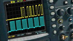
Measuring electricity is a lot different than measuring a piece of wood. When you take out your tape measure, you know the wood is 2 feet and 3/16 of an inch long. But we can’t see electricity, so we need a machine like an oscilloscope to interpret it and display it in a way we can understand like a voltage-time plot. So, we need to trust that the measurement is interpreting the electricity correctly, which involves a little more understanding of how it works than just believing the guy at the tape measure company put all the marks in the right place.
Related Articles
- What's The Difference Between Pre-Layout And Post-Layout PCB Simulation?
- Evaluate Feedback Stability When There's No Test Point
- How An Emerging Methodology Better Supports SoC Design
As speeds of electronics have increased over the years, so have the speeds and capabilities of measurement tools. They have made oscilloscope probes with higher bandwidth to be able to measure the faster signals and with higher impedance to minimize impact on the circuit operation. But speeds have increased so much that on-board measurements for many busses, specifically high-speed differential busses like PCI Express, have become impractical. For these signals, measurements must be taken using special test boards, such as the compliance test boards associated with PCI Express. This takes measurement even further from reality, but still not without great value.
In simulation, on the other hand, you can look anywhere in the circuit. This allows you to see inside ICs, past on-chip signal processing like equalization, which is essential for evaluating the performance of high-speed differential links in the multi-gigabit range. However, to do so, all the pieces of the bus must be modeled accurately.
Types Of Simulation And Measurement
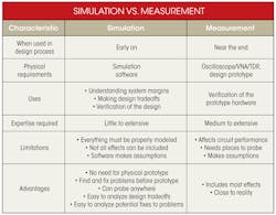
There are many types of simulation for electronics: digital, analog, signal integrity, power integrity, and even thermal simulation (see the table). One of the most common simulation types used in modern electronics is signal integrity, which focuses on the analog characteristics of digital busses. The main goal of signal integrity simulation is to verify that the digital ones look like ones and zeros look like zeros, which is done by analyzing voltage-time waveforms of the signals. These waveforms are usually viewed as a series of several bits, or sometimes very long strings of bits overlaid on one another, which is called an eye diagram.
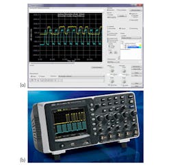
Signal waveforms also can be measured on an oscilloscope. The oscilloscope is connected to the signal’s receiver on a printed-circuit board (PCB) via a probe or SMA cables, which allows it to capture the signal waveform. The oscilloscope can be placed in a mode that builds an eye diagram by measuring a data stream for a very long series of bits, and each measurement sampling point is laid on top of one another until a picture is created that shows the relative “density” of the points captured. Points of higher density appear as different colors in the eye diagram (Fig. 1).
Eye diagrams are one of many types of signal waveforms used in signal integrity analysis. They are relatively easy to evaluate. An open eye means a passing condition, and a closed eye means failure. Other types of waveforms are also analyzed. For instance, for a parallel bus, a clock and data signal often must be compared against one another to ensure that timing specifications are met. Another type of simulation is a crosstalk simulation, where coupled nets are analyzed to see what noise is coupled from one signal to the next.
To generate these waveforms, the simulation tool must have knowledge of the behavior of the I/O buffers on a chip, the internal timing of the chip, the parasitics of the package, the behavior of the traces on the board, and any other pieces of the interconnect, like vias, pins, and connectors. All of these components of a simulation have associated models. I/O buffer models include IBIS, Spice, and VHDL-AMS.
Package and S-parameter models are usually in Spice or S-parameter format. Models for the interconnect are generally created natively in the simulation tool and require some type of two-dimensional or three-dimensional field solver. All of these models are passed into a circuit simulator that generates the waveforms to be analyzed. And, of course, all of these models need to be accurate if the simulation results are expected to match the measured waveforms.
However, waveforms aren’t the only type of result generated from simulations and measurements. With the proliferation of faster and faster serial interconnects in the multi-gigahertz realm, the emergence of jitter and bit error rate (BER) analysis have accompanied the need for eye diagrams. Jitter is basically the time-variance of edges in a data stream, and it results in closure of the eye diagram.
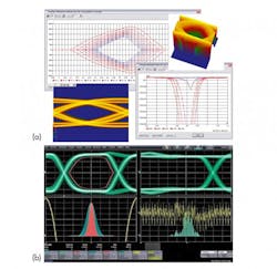
There are many sources of jitter in a link, and each type of jitter has a unique signature. Jitter can be sinusoidal, uniform, or Gaussian, for example. Many sources of jitter are inherently part of a regular simulation, like inter-symbol interference (ISI), which is created when running long sequences of random bits, while others can be added independently to the simulation. Similarly, different sources of jitter can be extrapolated from a measured eye and measured on an oscilloscope (Fig. 2).
Some sources of jitter, like thermal noise on ICs, cannot be simulated. But because their distribution is known to be Gaussian, they can be artificially added to a simulation. This allows the simulation to mimic the random jitter that exists on all waveforms and can be seen in measurement. In fact, thermal noise is the main source of random jitter in electronic circuits. And, since its distribution is Gaussian, it is boundless, meaning that eventually all eye diagrams will close. This is why eye masks are defined with different BERs.
Jitter can also be examined in terms of BER and “bathtub curves,” such as the ones in Figure 2, and can be created from the signal waveforms to describe that relationship. Similarly, in simulation, eye contours at different BER levels can be created to predict the performance. Identifying performance to very low levels of BER is something that would be very difficult to measure, as it would require capturing samples of a data stream on an oscilloscope for months and possibly years.
The physics and mathematics of electromagnetics have been well understood for decades. The key to making an effective simulation tool, however, is being able to generate practical computational performance levels without sacrificing accuracy. And this is only one part of the problem. The other is making sure you are accurately modeling physical structures.
On a PCB, for instance, one of the most important things to model correctly is the board stack-up. This means understanding exact dielectric heights used by the board manufacturer and the properties of the dielectric material, specifically the dielectric constant and the loss tangent. Additionally, the copper used on the board must be modeled properly, including the precise copper weight, changes in trace widths from the etching process, and the actual texture, or surface roughness, of the copper.
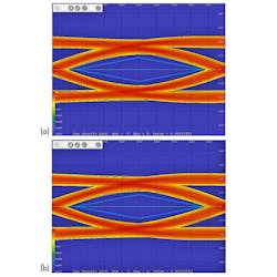
Improper board stack-up modeling is one of the main sources of discrepancy that can exist between a simulation and a measurement. Correlation studies are incredibly useful exercises for determining sources of error in your simulation and measurement process. Figure 3 shows the results of an example study.
Since several models are used in a simulation, errors in any one of them can lead to erroneous results. The number of sources of error generally increases with increasing frequency and desire for more exact correlation. Models can be grouped into two main areas: chip and board.
The chip models include I/O buffer models and packages. Chips are generally more difficult to characterize and require specialized equipment. You can measure a chip’s transmitting behavior by running it into a text fixture and measuring the resulting waveform with an oscilloscope. This is of limited usefulness, though, as the chip operation will usually be affected significantly by the system in which it is placed.
The board, on the other hand, can be characterized quite well because it is a passive device. There are measurement devices specifically designed to measure boards. A vector network analyzer (VNA), for example, adds a stimulus to the board interconnect and measures the amount of energy transmitted through the interconnect and reflected by the interconnect. The stimulus used is a sine wave at a range of different frequencies, which helps provide a frequency-based model of the interconnect called a scattering parameter or S-parameter.
Another measurement device, a time-domain reflectometer (TDR), can characterize an interconnect by similarly looking at reflected and/or transmitted energy, but instead using an edge (low-to-high transition) as the stimulus. These measurement devices can accurately characterize an interconnect and are extremely valuable in helping to identify sources of error between simulation and measurement.
As simulation and measurement technology continues to advance, we gain a greater understanding of the capabilities and limits of the electronic devices we design. The capabilities of each complement one another and allow us to continually improve our design processes to be more efficient and to design higher-performing, reliable hardware that continues to push the limits of performance generation after generation.
Correlation Study: Analysis Anchored in Reality
Measurement correlation is just a stackup away
Your traces aren’t square, but do you need to care?
This file type includes high resolution graphics and schematics.
About the Author
Patrick Carrier
Product Marketing Manager for High Speed PCB Analysis Tools
Patrick Carrier has more than a decade of experience in signal and power integrity. He worked as a signal integrity engineer at Dell for five years before joining Mentor in September 2005, where he is a product marketing manager for the high-speed PCB analysis tools.
Chuck Ferry
Product Marketing Manager for High Speed Tools
Chuck Ferry is product marketing manager for high-speed tools at Mentor Graphics, focused on product definition for signal integrity and power integrity solutions. He has spent the last 14 years tackling a broad range of high-speed digital design challenges spanning from system level mother board design to multi-gigabit channel analysis. He graduated from the University of Alabama in Huntsville with a BSE in electrical engineering and continued graduate course work in signal processing and hardware description languages.
