Members can download this article in PDF format.
Signal chains incorporating devices such as analog-to-digital converters (ADCs) or digital-to-analog converters (DACs) often require a voltage reference to assist in the measurement or creation of a precise analog signal. Systems ranging from semiconductor test equipment to medical ultrasound scanners can benefit from references that exhibit minimal gain and noise errors to optimize precision. When choosing a voltage reference, you need to consider potential error parameters ranging from initial accuracy to long-term drift due to aging.
Sponsored Resources:
- Voltage reference design tips for data converters
- Long-term drift in voltage references
- REF70 2 ppm/°C maximum drift, 0.23 ppmp-p 1/f noise, precision voltage reference
Voltage-Reference Errors
Several specifications indicate sources of possible voltage-reference errors. Initial accuracy specifies how close a reference voltage is to its nominal level at 25°C. Solder shift refers to the effect of the thermal shock of the solder process on a reference device’s initial accuracy. Temperature drift indicates the change in reference voltage over a system’s operating temperature range. And line regulation indicates shifts in the reference-voltage output resulting from changes in the reference device’s power-supply voltage.
System calibration can reduce many voltage-reference errors, including gain and offset-voltage errors. Calibration can occur at the factory, at system startup, or during runtime. Factory calibration eliminates the need for additional system components to enable startup or runtime calibration, although it can’t account for effects such as drift due to aging.
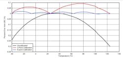
Single-point calibration occurs at one temperature, such as 25°C or the expected system operating temperature. If your system will operate over a wide temperature range, you might consider multipoint calibration.
In the Figure 1 example, a three-point calibration decreases the temperature drift by a factor of three, and a six-point calibration decreases the error by a factor of 10. Keep in mind, though, that multipoint calibration increases cost and calibration time, and some devices have temperature curves for which calibration is difficult. A better option might be to choose a voltage reference with lower temperature drift that doesn’t require multipoint calibration.
Voltage references also are subject to noise errors, which can’t be completely calibrated out. For instance, 1/f noise, also known as flicker noise, occurs in the 0.1- to 10-Hz range and is difficult to filter out because of the low frequency. To minimize 1/f noise errors, choose the lowest reference voltage allowed by your application (1/f noise scales with voltage level) and opt for a device with a low 1/f noise spec.
Broadband noise, also called wideband noise, has a flat response that spans the entire system frequency range. You can filter out much of this noise with an RC filter or digital filtering techniques.
Another key specification is power-supply rejection ratio (PSRR), a translation factor of the input noise to the output. You can improve PSSR performance by powering the reference with a low-dropout regulator (LDO) instead of a switching supply. Adding a large power-supply decoupling capacitor can help improve PSRR when a noisy supply must be used.
Long-Term Drift
For many industrial and automotive applications, long-term drift (LTD), also called long-term stability, is a critical parameter. Long-term drift is an estimation of deviations in reference voltage over time due to aging and the accompanying changes in stress on the voltage-reference die. In general, a larger package size for a given die will result in lower LTD. In addition to package size, contributors to LTD include the mold compound, PCB design, and environmental moisture.
LTD datasheet values are based on measurements taken at a time t0 right after soldering and again at a time tn after n hours of operation at a specified temperature. Texas Instruments performs LTD tests on fully automated multisite bench setups. An oil bath maintains a steady 35°C temperature (±0.01°C) for the test devices, which remain powered on. An 8.5-digit digital multimeter (DMM) records voltage every half hour.
Figure 2 shows long-term drift parameters for Texas Instruments’ REF34-Q1 device in two package styles. A gain-error breakdown analysis of the REF34-Q1 with no calibration shows that LTD typically accounts for 12.8% of the total error over a 10-year lifespan, vs. 27.4% for initial accuracy (based on datasheet maximum value), 5.49% for solder shift (based on datasheet typical value), and 54.3% for temperature drift (based on datasheet maximum value). With calibration, LTD accounts for 19.1% of the total error, vs. 80.9% for temperature drift.
As Figure 2 suggests, LTD tests can run for 1,000, 2,000, or even more hours. A mathematical approach exists that provides a conservative estimate of LTD over a system lifetime that may reach 10 years.
Typical devices exhibit the most drift over the first 100 hours of operation due to factors such as mold curing. To minimize LTD’s impact, bake the device can be baked in a power-on condition before calibration. In addition, you can perform routine calibration in the field, or, if that’s not feasible, delay the initial calibration as long as possible—preferably until just before installation or commissioning in the field.
Precision Voltage Reference
Texas Instruments’ REF70 serves as an example of a precision voltage reference. It offers an initial accuracy of 0.025% (max) and a temperature coefficient of 2 ppm/°C (max). 1/f noise (from 0.1 to 10 Hz) is 0.23 ppm p-p, and PSRR is 107 dB at 1 kHz. Available in a humidity-resistant hermetically sealed ceramic package, the reference offers long-term stability (1,000 hours) of 28 ppm.
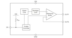
Designed for a wide range of applications, the REF70 (Fig. 3) offers an input-voltage range up to 18 V, an output current of ±10 mA, and an operating temperature range of −40 to +125°C. Voltage options include 2.5, 3, 3.3, 4.096, and 5 V.
Among its applications are semiconductor test equipment, data-acquisition systems, precision weight scales, industrial instrumentation, analog I/O modules, field transmitters, and power-monitoring equipment. For noise-sensitive medical applications, the REF70 helps enable low-noise measurements from the analog front end of ultrasound scanners and X-ray systems.
Conclusion
A precision reference is critical for many automotive, industrial, and medical applications. Closely evaluating potential gain and noise error sources and taking care to minimize them can help ensure your project’s success over its anticipated lifetime.
Sponsored Resources:


