Members can download this article in PDF format.
Designers of EV battery charging stations, inverters, and other power converters are beginning to take advantage of the newer wide-bandgap (WBG) semiconductors like gallium nitride (GaN) and silicon carbide (SiC) in addition to new circuit designs such as the active neutral center clamp (ANPC). They’re helping to boost efficiencies and create smaller size products.
SiC and GaN MOSFETs provide the fast switching at higher voltages and current levels. IGBTs also are widely used at the higher voltage and current levels. Newer designs like ANPC permit the modularity that allow converters to be stacked to provide the desired output power. Besides EV battery chargers, other applications like solar inverters can benefit by adopting these new methods.
What’s an ANCP?
The active neutral point clamp is an improved version of the widely used half-bridge circuit that’s the basis for most power circuit design (Fig. 1). Several other improved variations also have been developed, such as multilevel converters and the neutral point clamp (NPC). Multilevel converters have more than one switch per half bridge leg.
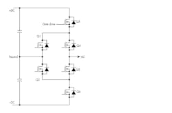
The ANPC uses another arrangement as shown in Figure 2. This is the basic building block of an ANPC inverter. The half bridge is evident (Q3-Q6), while Q1 and Q2 form the clamp to ground or neutral. Turning on Q1 and Q2 simultaneously clamps the output to ground. Other operations include turning on Q3 and Q6 or turning on Q1and Q4. This provides three output levels: +DC, -DC, and ground.
All MOSFET gates receive their input from an MCU controller via a gate-driver circuit. Significant differences exist between GaN and SiC gate-drive requirements and packaging variations. A wide range of output waveforms can be implemented by programming the gate-drive pulses to boost power or otherwise change it to fit the current need or application.
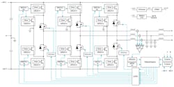
Combining multiple inverters shown in Figure 2 forms the three-phase ANPC power unit (Fig. 3). Texas Instruments has a complete reference design for a 6.6-kW, three-phase, three-level ANPC power module for use in inverters and PFC input stages.
How to Design an Efficient, Powerful, and Fast EV Charger
The driving force behind all of this recent power-converter design activity is the need to define and create a nationwide network of charging stations for the forthcoming glut of electrical vehicles. EVs aren’t particularly popular right now due to their high price, the lack of a critical mass of charging stations, and the long charging times. Consumers fear range anxiety because of the dearth of places to recharge. And the charging time is off-putting.
EVs represent only a few percent of overall car sales, but more are on the way. Unexpected government mandates could force the country to go electric sooner than not.
Building a network of charging stations comparable to our gasoline stations is an enormous challenge. There are so many unknowns. Can the current grid handle a massive, although gradual, increase in charging?
The current conditions dictate some priorities such as the long charge time. A standard home EV charger can use up to 6.6 kW, and it will take from eight to 17 hours for a full charge. That’s okay for a home charger used at night, but simply unacceptable for daily use and long trips.
The answer is to go directly to the available dc charging option. The option bypasses the vehicle’s onboard charger (OBC) and charges the main battery bank with dc at a level in the 600- to 1000-V range. An 80% charge typically takes about 30 minutes, a reasonable time. So, these are the guidelines for defining and building the charging equipment and the new network.
Conservative designs will factor in some of the unknowns and create equipment that will have a reasonable life. The first is efficiency. Luckily, virtually all new EV charging equipment is highly efficient—90% or more. Individual items can almost reach the 98-99% level.
To achieve that degree of efficiency requires the use of the WBG semiconductors like SiC MOSFETs. Newer GaN devices work well, too. They have fewer losses and switch at speeds that reduce power loss. Switching at frequencies up to 100 kHz also permits the use of smaller magnetic components and capacitors. They cost less and take up less space, helping to reduce equipment size. The newer devices also handle voltages up to 1500 V and currents in the tens of amperes. The reference design mentioned earlier achieves 98.5% peak efficiency.
Next are the new circuit designs, with the best example being the aforementioned ANPC. Bidirectional converters also are a benefit, or necessity, in the latest designs. Another key factor is that the equipment be expandable to handle higher loads. Some of the new circuits are easy to modularize—creating stackable modules offers considerable future flexibility, with many other topologies to choose from.
Building Out a Charging Network
The best starting place is to evaluate the primary power source—the national grid. Actually, several grids in the U.S. are tied together to form the overall power source. Can it handle the extra load of EV charging? One source indicates that the current grid can manage the charging levels of today. However, when the total number of EVs reaches about 15% of all vehicles, the grid will feel the load.
Beyond that considerable investment, an updated and expanded grid will be needed. California plans to phase out all gasoline vehicles by 2035, so it will feel the pressure to update earlier. Other projections show a need of a massive investment by 2050 based on EVs being 66% of the total number of vehicles. Some utilities had hoped they could put their excess wind and solar energy toward this need, but at current levels; the extra available energy is just not needed. Phasing out all gasoline vehicles isn’t a good idea in some areas.
Again, it is wise to design charging-station equipment to be flexible and most importantly efficient. Modular stackable circuits provide the flexibility to adapt to most needs. Other factors depend on the needs of a mix of variables such as types and power levels of EV. What is the mix between ac and dc charging?
- Use the latest SiC or GaN devices to provide the high-voltage capability and switching speed.
- Choose a topology that fits best with the station planning and delivers the maximum efficiency.
- Use the best connectors available. Multiple charger-to-vehicle types are used and all must be very robust for continuous use.
- Remember that when working with low and high voltages, some electrical isolation will be needed. TI has a line of capacitive isolation ICs that will work.
- Consider thermal design to be a key element. Think of the heat generated while charging eight 120-kW vehicles at the same time.


