Class AB Op Amps: The Solution for Low-Iq Audio
This article is in TechXchange: Why Low Iq is the Smart Thing to Do
Members can download this article in PDF format.
What you'll learn:
- Different classes of amplifiers.
- What are the benefits of class AB amplifiers?
- Patents that address the quiescent current of class AB amps.
Amplifiers have many classifications, and each class has its advantages and disadvantages. The different classes of amplifiers are A, B, AB, C, D, E, F, T, and even more “alphabet soup.” Designers typically work with classes A, B, AB, and C.
The class A amplifier has high linearity with high gain ability. It has a 360-degree conduction angle that leads to the amplifier remaining in the active state at all times, and it’s able to use the entire input signal. The class A amp has good high frequency and feedback-loop stability. A drawback is that it only has 25% to 30% efficiency.
Class B amplifiers use two active devices that are biased one-by-one, each in half of the actual full cycle, meaning that every device will only be biased during 180 degrees of the cycle. Two transistors provide the combined current drive to the load. This improves the efficiency as compared to the 25% to 30% efficiency of the class A amp.
Class C amplifiers operate in two different operating modes, tuned or untuned (class C amps have a huge distortion across their output). The efficiency of this amplifier is much higher than the A, B, or AB: A maximum 80% efficiency can be achieved, especially in radio-frequency-related applications.
What is a Class AB Amplifier?
Class AB amplifiers overcome the cross-over distortion that plagues class B amplifiers. The class AB amplifier, which combines class A and class B amps, eliminates the low-efficiency issues of class A amplifiers, and reduces the distortion and improves on the poorer linearity exhibited by class B amps.
Class AB push-pull amplifier
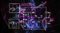
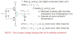
To create a basic class AB amplifier stage, designers need to take a class B push-pull stage and bias both transistors slightly into conduction mode (this dc bias method will keep the transistors in the conduction mode even with no input to the transistor bases) (Fig. 1).
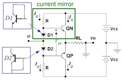
The class AB amplifier is a type of push-pull amplifier that’s similar to a class A push-pull amp. The only difference is that two biasing resistors, both designated R in Figure 2, are chosen to enable the transistors to be biased just at the cut-in voltage of 0.7 V. This reduces the time when both transistors are simultaneously OFF (the time in which the input signal is between −0.7 and +0.7 V), leading to a reduction in cross-over distortion.
The class AB configuration has a reduced efficiency and dissipates a reasonable amount of power while in the zero-input condition. Class B has the highest efficiency at 78.5%, followed by class AB, which is between 78.5% to 50%, and then class A at 50%. In terms of distortion, class A has the lowest, followed by class AB, with class B bringing up the rear.
Audiophiles, or “Golden Ears” as we called them in my audio days at Empire Scientific Corporation during the 1970s, typically like class AB amplifiers because of their “warmth” or “coloration,” which was really relished at the digital amplifier outputs.
Many “Golden Ears” claim that digital amplifiers are less likely to “color” the sound. Analog amplifiers are particularly useful for the mid- and high-ranges due to this “coloration.” That’s why they’re preferred in the amplifier substages, since the signal starts out more like the original recordings.
A disadvantage of the class AB amplifier is that temperature matching of each current mirror will be necessary, especially when emitter degeneration resistors aren’t used, such as in Figure 2.
Quiescent Current in the Class AB Amplifier
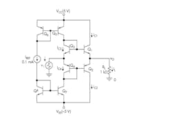
In Figure 3 (from a book2 written by my friend, Professor Sergio Franco), when vo = 0, the RL load will be zero. This leads to Q1 and Q2 carrying identical currents, or IC1 = IC2. If we assume that Q1 – Q3 and Q2 – Q4 pairs are both matched, then Q1 will mirror Q3 and Q2 will mirror Q4 to give iC1 = iC2 = 0.1 mA. This is the quiescent current (Iq) of the Q1 – Q2 pair.
When iL = 0, the circuit is in standby mode.
Class AB Patents Regarding Quiescent Current
A temperature-independent class AB amplifier stage design
Many class AB amplifiers have an output Iq that will vary with temperature; compensation diodes can be added to minimize this issue. If we try adding emitter degeneration resistors, it will increase the output impedance of the stage. Designers need another means to stabilize the output Iq, in such a way that will provide independence from temperature, without using compensation diodes, that will increase the output impedance of the stage.
Back in 1984, my friend and colleague, Ron Quan, patented a constant-quiescent-current, class AB amplifier stage design, patent number US4458213A, which stabilizes the amplifier output Iq, leading to temperature independence. Quan’s invention relates to amplifiers and drivers, and particularly to audio power amplifiers, video amplifiers, as well as servo-motor drive amplifier applications.
Here’s a summary of Quan’s circuit:
This circuit enables the quiescent collector current of an output transistor amplifier to be constant via sensing the voltage, which is developed across a resistor connected in series with the output transistor's collector. A differential amplifier is employed to produce a first signal representative thereof that’s sampled and held by a circuit controlled via a zero-voltage-crossing detector sensitive to the amplifier output voltage. The sampled and held signal becomes inverted and integrated with respect to an adjustable reference voltage, producing a second signal. This second signal controls the current passed by a transistor, connected in a voltage divider network, supplying the base bias voltage to the output transistor.
A class AB amplifier allowing quiescent current and gain to be set independently
This patent (5,512,857), for class AB amplifier topologies, shows reduced quiescent power.3 Each of the output transistors is biased to conduct only a small quiescent current that reduces amplifier distortion. Class AB amplifiers are used in low-voltage power-supply applications (1-V power supplies are not uncommon here) such as hearing aids. This low-voltage power-supply level allows for the use of a single-cell battery.
Class AB amplifiers are far superior to class A amplifiers in minimizing power consumption. Also, these amplifiers will be a better choice than class B amps in minimizing crossover and harmonic distortion.
One major problem with prior art class AB amplifiers in this application is that there’s a tradeoff of reduction of quiescent power dissipation and distortion vs. available output power. These prior art designs aren’t able to lower both power dissipation and distortion to a minimum level, nor maintain the needed output power capacity.
This patent also discusses a prior art Class AB amplifier that maintains the gain characteristics of the class AB amplifier and reduces its power dissipation as well, but does not improve power consumption. These prior art amplifiers were all not able to maintain the gain characteristic as well as reduce power dissipation since quiescent current was not able to be independently controlled from the circuit current gain. Patent (5,512,857) solves that problem.
Read more articles in TechXchange: Why Low Iq is the Smart Thing to Do
References
1. ESE319 Introduction to Microelectronics, Kenneth R. Laker, University of Pennsylvania, 11/26/2012.
2. Analog Circuit Design: Discrete & Integrated, Sergio Franco.
3. “A class AB amplifier allowing quiescent current and gain to be set independently,” US Patent 5,512,857 dated April 30, 1996.
About the Author

Steve Taranovich
Freelance Technical Writer, Phoenix Information Communication LLC
Steve is a contributing editor to Electronic Design.
Author of the non-fiction “Guardians of the Right Stuff,” a true story of the Apollo program as told by NASA and Grumman Corp. engineers, an astronaut, and technicians.
Experienced Editor-In-Chief of EETimes/Planet Analog and Senior Technical Editor at EDN running the Analog and Power Management Design Centers from 2012 to 2019.
A demonstrated history in electronic circuit design and applications for 40 years, and nine years of technical writing and editing in industry. Skilled in Analog Electronics, Space-related Electronics, Audio, RF & Communications, Power Management, Electrical Engineering, and Integrated Circuits (IC).
1972 to 1988 worked as a circuit design engineer in audio (8 years) and microwave (8 years). Then was Corporate Account Manager/applications engineer for Burr-Brown from 1988 to 2000 when TI purchased Burr-Brown. Worked for TI from 2000 to 2011.
Strong media and communication professional with a BEEE from NYU Engineering in 1972 and an MSEE from Polytechnic University in 1989. Senior Lifetime member of IEEE. Former IEEE Long Island, NY Director of Educational Activities. Eta Kappa Nu EE honor society member since 1970.


