How to Design a Good Vibration Sensor Enclosure (Part 2)
This article is part of the Analog series: How to Design a Good Vibration Sensor Enclosure
Members can download this article in PDF format.
What you'll learn:
- Rectangular or cylindrical? Comparing the enclosure types.
- Determining wall thickness.
- How does the enclosure's orientation impact performance?
In Part 1, we covered modal analysis, the Timoshenko differential equation of vibration, and the type of material to use for a design. Here, we’ll cover whether to use a rectangular or cylindrical enclosure, maximum recommended height, the effect of wall thickness, and the impact of orientation on performance.
Should I Design a Rectangular or a Cylindrical Enclosure?
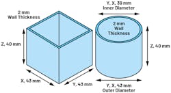
Figure 1 shows both a hollow rectangular and cylindrical stainless-steel extrusion, with 2-mm wall thickness and 40-mm height. The outer diameter of the cylinder is 43 mm, and the rectangular piece is also 43 mm on both x and y axes.
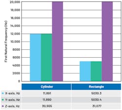
For modal analysis, the entire 2-mm wall surface (or x, y cross-sectional area) is a fixed constraint. Figure 2 shows modal finite-element-method (FEM) analysis results. The first natural frequency with significant mean power frequency, or MPF (greater than 0.1 for the ratio of effective mass to total mass of the system), is plotted vs. material shape. The cylindrical shape has the highest first significant natural frequency for x and y axes, with similar performance in the z direction.
Geometry: Area and Inertia
Equation 1 includes both material and geometric dependencies. As both rectangular and cylindrical pieces were simulated using stainless-steel parameters, the only reason for better performance with the cylindrical piece is geometry.
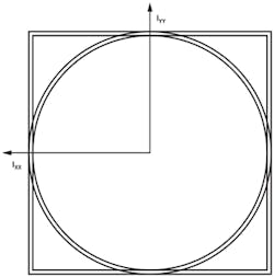
Figure 3 illustrates the cylinder and rectangle cross-section for calculation of the area moment of inertia and cross-sectional area of the pieces.
The area moment of inertia (IYY) of the rectangle is almost 50% greater than that of the cylinder (Table 1). The rectangle is better at withstanding deformation. However, the cross-sectional area (A) of the cylinder is 3X larger than the rectangle. A larger A parameter means a larger fixed constraint both in simulation and reality—the cylinder is better designed for increased rigidity or higher stiffness.
Using the Table 1 values and Equation 2, the critical frequency is 60.74 kHz for the cylinder and 26.56 kHz for the rectangle. Equation 2 is a useful tool to show the relative performance of different geometries. Equations 1 and 2 predict four independent solutions below the critical frequency.
Table 2 summarizes the FEM results and confirms the first four significant modes.
What’s the Maximum Recommended Height for My Sensor?
Equations 1 and 2 are useful, but they don’t provide analytical guidance on the tradeoff between the vertical height of the enclosure and the first significant natural frequency possible. From Equation 3, we can intuitively see that the taller the sensor enclosure, the lower the first natural frequency.
Limitations of Analytical Models
Equations 1 and 2 assume that the width of a beam cross-section is at least 15% of the beam length.5 Other approaches for long, thin beams, such as Bernoulli’s equation,6 assume that the width of beam cross-section is less than 1% of the beam length.5
For long, thin beams, Equation 46 can be used, which includes length (L) or sensor height. Equation 4 doesn’t consider shear forces, which are important for short, thick beams. For first significant natural frequencies, there’s generally good agreement between equations 1,2, and 4 for solid cylindrical shapes. For hollow shapes, Equation 4 underestimates the first significant natural frequency by 50%.
Equation 46 parameters include Young’s modulus (E) of stiffness, diameter (d), length (or height), density of material used (ρ), and Kn constants for given configurations.
As analytical models fail to provide guidance for height constraints for hollow enclosures, height studies typically rely on FEMs.
Height Study
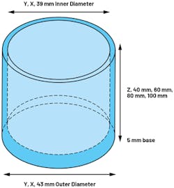
To provide guidance on performance degradation with increased enclosure height, the models shown in Figure 4 were simulated.
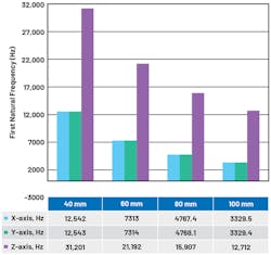
The stainless-steel extrusions include a 5-mm base, which can be used to provide a stud screw mount between the enclosure and monitored equipment (for example, a motor). Increasing the height of the cylinder from 40 mm to 100 mm results in a reduced first significant natural frequency of 12.5 kHz to 3.3 kHz for x- and y-axes (Fig. 5). The z-axis also reduces from 31.2 kHz to 12.7 kHz. For high-performance sensors, it’s clear that the enclosure height must be minimized.
What is the Effect of Reducing Enclosure Wall Thickness or Diameter?
Reducing Enclosure Wall Thickness
Table 4 shows the geometric and material properties when the cylinder in Figure 1 is reduced from a 2- to a 1-mm wall thickness, but keeps the 40-mm height and 43-mm outer diameter.
Using the Table 4 values and Equation 2, the critical frequency is 60.74 kHz for the 2-mm wall-thickness cylinder and 61.48 kHz for the 1-mm wall-thickness cylinder. With both IYY and A parameters decreasing by about 50%, the numerator and denominator in Equation 2 are equally affected for the 1-mm wall-thickness cylinder. From this calculation, it’s assumed that both cylinders will perform similarly in FEM modal analysis.
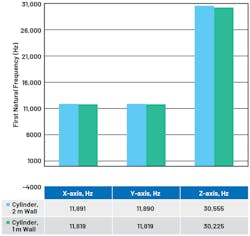
In Figure 6, the FEM results of first natural frequency with significant MPF (greater than 0.1 for the ratio of effective mass to total mass of the system) is plotted vs. cylinder wall thickness. The effect of reducing the cylinder wall thickness compared to natural frequency is very small.
Reducing Enclosure Diameter
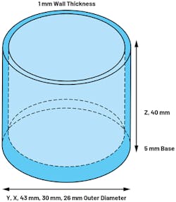
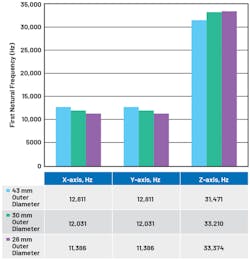
The examples presented so far have all focused on cylindrical enclosures with a 43-mm outer diameter. Some designs may only require 30- or 26-mm outer diameters. Figure 7 illustrates the simulation model, and Figure 8 shows the effect of varying the outer diameter of the enclosure.
When reducing the cylinder diameter from 43 mm to 26 mm, the x- and y-axes’ first natural frequencies reduce by about 1.5 kHz, while the z-axis first natural frequency increases by 1.9 kHz. In changing the cylinder diameter, both the area moment of inertia (IYY) and the cross-sectional area (A) decrease. The IYY parameter will decrease more than the A parameter.
In reducing the diameter from 43 mm to 30 mm, the IYY will reduce by 2/3, while the A will reduce by 1/3. Again, referencing Equation 2, the net effect is a gradual decrease in first natural frequency.
Intuitively, reducing the cylinder diameter will make the structure less rigid, so it makes sense that the natural frequency will reduce. However, using simulation, it’s clear that the reduction in first natural frequency isn’t dramatic, and changing diameters can still result in a first natural frequency in the tens of kilohertz.
Will Changing the Sensor Enclosure’s Orientation Increase Performance?
The previous sections of this article show that increasing the height of the enclosure will result in a reduced first natural frequency. Also shown was that using a cylindrical enclosure shape is recommended instead of using rectangular shapes. However, in some cases, rectangular shapes are useful.
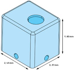
Consider a scenario where the enclosure needs to accommodate a sensor and circuit, with a defined 60-mm height and 43- × 37-mm breadth and width. Using a rectangular shape and changing the orientation of fixed constraint (equipment attachment) can help boost performance.
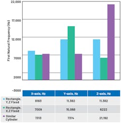
The rectangular enclosure shown in Figure 9 has multiple attachment holes; thus, the enclosure can be mounted to equipment in various orientations. If the enclosure is mounted on the x, z face, then the effective height of the enclosure is 60 mm. However, if the enclosure is mounted on the y, z face, then the effective height is only 37 mm. This approach can be used for a rectangular enclosure, but it’s not feasible using a cylinder’s curved surface.
Figure 10 shows that by changing the enclosure orientation, the x-axis first resonant frequency can be boosted, and the y-axis is better when compared to a cylinder. The z-axis first resonant frequency is higher for the y, z fixed orientation compared to the x, z fixed orientation, with almost double the frequency mode. However, the cylinder performs the best—by far—for z-axis natural frequency. A rectangular shape is a good approach to have similar performance across three axes in comparison to a cylindrical shape.
In Part 3, we’ll cover design with a single-axis and triaxial sensors, design and modal analysis, external cable simulation, and vibration sensor mounting.
Read more articles in the Analog series: How to Design a Good Vibration Sensor Enclosure
References
1. ANSYS Innovation Courses: Modal Analysis. ANSYS, 2021.
2. Stephen Timoshenko. Vibration Problems in Engineering, 4th edition. John Wiley and Sons Inc., New York, 1974.
3. Leszek Majkut. “Free and Forced Vibrations of Timoshenko Beams Described by Single Difference Equation.” Journal of Theoretical and Applied Mechanics, Vol. 47, No. 1, January 2009.
4. Mohammad Hossein Abolbashari, Somayeh Soheili, and Anoshirvan Farshidianfar. “Flexural Vibration of Propeller Shafts Using Distributed Lumped Modeling Technique.” The 16th International Congress on Sound and Vibration, Krakow, 2009.
5. Saida Hamioud and Salah Khalfallah. “Spectral Element Analysis of Free - Vibration of Timoshenko Beam.” International Journal of Engineering, 2018.
6. Olivier A. Bauchau and James I. Craig. Structural Analysis: With Applications to Aerospace Structures, Springer, 2009.
7. TN17: Installation of Vibration Sensors, Wilcoxon Sensing Technologies, 2018.
8. A. Khayer Dastjerdi, E. Tan, and F. Barthelat. “Direct Measurement of the Cohesive Law of Adhesives Using a Rigid Double Cantilever Beam Technique.” Society for Experimental Mechanics, May 2013.
9. ANSYS Innovation Courses: Fundamental Topics in Contact. ANSYS, 2021.
10. Ansys Maxwell: Low Frequency EM Field Simulation. ANSYS, 2021.
About the Author
Richard Anslow
System Applications Engineer, Analog Devices
Richard Anslow is a systems applications engineer with the Connected Motion and Robotics Team within the Automation and Energy business unit at Analog Devices. His areas of expertise are condition-based monitoring and industrial communication design. He received his B.Eng. and M.Eng. degrees from the University of Limerick, Limerick, Ireland.
