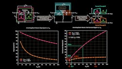
How to Leverage the Inverting Buck-Boost in High-Voltage Apps (Download)
A variety of topologies can be considered for applications that require the generation of a negative voltage rail, as illustrated in the article “The Art of Generating Negative Voltages.”1 However, if the absolute voltage at the input and/or output can exceed 24 V and the required output current may reach a few amperes, the charge pump and the negative LDO regulator are to be discarded due to their low current capability. Also, the size of their magnetic components causes the flyback and the Ćuk converter solutions to become quite cumbersome. As a result, under such conditions, the inverting buck-boost provides the best compromise between high efficiency and small form factor.
To reap these benefits, though, the operation of the inverting buck-boost topology under high-voltage conditions must be fully understood. Before diving into such details, we will begin with a brief review of the inverting buck-boost topology. Then, we will compare the critical current paths of the inverting buck-boost, buck, and boost topologies.
